
Radio Control: Scale
Bob and Dolly Wischer
Scale documentation
Requests for information regarding documentation material continue to arrive in our mailbox. Doubts usually arise in the hearts of competition Sport and Giant Scale modelers when faced with having to supply photos of obscure aircraft, or those that have been neglected in historical information. If a three-view drawing is available, and the drawing shows color data, photos aren't required.
When a three-view drawing alone is the complete documentation, it becomes a one-sheet presentation. To supplement this drawing, some modelers will include several additional sheets of printed data about the prototype, not realizing that judges have very little time to do extensive reading. When we consider that each judge would have to spend time absorbing the printed material, there would be much less time for the actual comparisons of drawing or photos with the model. It is to the contestant's benefit not to distract the judges from their duties by including extraneous material in the presentation. The six-page maximum limit on documentation was intended to shorten judging time.
What judges should be expected to read is the signed declaration listing the major components of the model that were not made by the builder. The declaration is not one of the six pages in the presentation, unless that page is also used to describe details of color and markings from a reliable source, or other such data. Short notes of a few words can be used with the three-view or photos to direct the judges' attention to something of importance, but generally it can be expected that lengthy written information will be ignored.
When a drawing isn't available, photos may be substituted, but these must show shapes in sufficient detail so that the model can be properly judged. For example, a side-view photo will not serve to inform judges of the wing and stabilizer shapes. A common error, and one that has proven the undoing of some fine examples of contest modeling, is to furnish a quantity of photos, none of which depict the exact airplane modeled. Using photos of a variety of prototypes is certainly permissible to show details and shapes, but most photos should be of the exact airplane modeled. It is preferable for all of the photos to be of the subject aircraft to permit checking the location of markings and color separation lines from all angles of view. The rule states specifically that the selection of photos are to be of the aircraft modeled.
In the beginning of the Sport Scale era, the six-page maximum documentation was thought to be a limitation to avoid an oversupply of material. Our recent observation of presentation booklets has shown that the greatest proportion of contestants have difficulty in filling more than a few pages. It's true, the rule book states that only a three-view, a plastic model, or a few photos will suffice as individual items, and any one of the three can be offered separately. On the other hand, if the modeler is serious about making a favorable impression on the judges and giving them worthwhile information, it is best to supply a combination of items. Of greatest value is the collection of sharp, clear photos, and these need not be in color. In fact, the prototypes of many of the models seen at contests were built before color photos were on hand. However, some sort of color documentation is an absolute necessity for a good static score.
Molded canopy
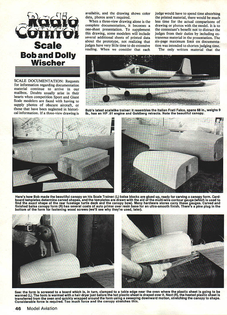
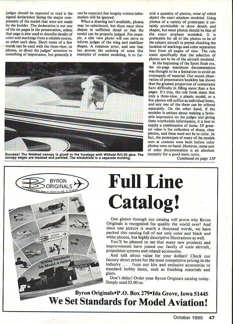
The canopy for Bob's new scalelike trainer is the largest we have ever molded. Size is limited by the width of our kitchen oven, which will accept a blank sheet of acrylic (Plexiglas) or butyrate sheet about 16 in. square. Acrylic sheet .031 in. thick has a self-adhesive paper protection on both surfaces. The sheet is cut by scoring deeply with a sharp blade on one surface, after which it is bent over a table edge to crack it through, much in the same manner of cutting glass. After cutting to size, the paper backing is removed.
Wood strips, 1/4 in. square, are screwed along opposite edges of the plastic sheet on about three-inch centers to provide a grip so that pressure can be applied for stretching the hot plastic later. Drill through the acrylic sheet carefully, as it tends to shatter from mild abuse. We clamp the wood strips to the top and bottom of the plastic while drilling through for wood screws. Hooks are then threaded into the wood so that the assembly can be hung in the oven in a horizontal position.
The heated plastic will be forcefully draped over a wooden form which is the exact shape of the desired canopy. Force is needed because the canopy has compound curves, side-to-side as well as fore-and-aft. We use balsa for the form, but any soft wood that lends itself to carving can be used. The form shape is established, and later checked, with cardboard templates with outlines to fit the fuselage. The advantage of this type of formed canopy is that it will fit snugly on the fuselage and doesn't need to be clamped in place while the cement hardens. A few pieces of masking tape hold its edges.
The form is given a smooth finish. Polyester resin will harden the surface, followed by several coats of filler. We use auto body filler. After sanding to a perfect finish, and no wood grain shows, with No. 180 and No. 320 silicon carbide paper, a final coat of clear epoxy produces an ultra-smooth surface. The form must be absolutely clean for a blemish-free canopy. Even a speck of dust leaves a tiny pimple in the softened plastic canopy material, and any visible wood grain will offend you.
Mount the wood form on a 1 x 2 in. pine board and clamp it to a table top so that the form is suspended over a clear space at the table edge. This will permit the heated plastic to be wrapped around the form bottom. Oven and form should be in close proximity to minimize cooling time in air while transferring the plastic sheet. While the plastic sheet is in the oven, heat the form with a hair dryer. Too much heat and the epoxy finish may blister. A cold form will cool the plastic so that a complete canopy cannot be draped in one quick downward sweep of the arms.
Oven temperature should be 250° to 300° F. Watch the plastic while it softens and begins to sag from its own weight. There may be some smoke visible from the canopy material during heating, indicating that it is ready for forming. Too much smoke and the material is overheated. In order to stretch over a compounded curved surface, the plastic must be uniformly rubbery, not slightly stiff, to be sure of easy conformity to the form. If not really soft, place it back in the oven for more heating time. A canopy that isn't completely in contact with the form due to premature cooling can be returned to the oven and re-softened. Heat will bring it back almost to its original rectangular shape, and it can then be used again. Wear gloves for the stretching operation, as the screw heads are very hot.
The plastic cools to room temperature in a minute, and the process can be accelerated by switching the hair dryer to its cold setting. In the first seconds after forming, even though still quite warm, the plastic has already taken a set and will not change shape. Throughout the forming process, it's best to have a helper. After cooling and removal of the wood strips, the acrylic can be cut with a Dremel grinding wheel or using abrasive cut-off discs or the fine-toothed circular saw cutting bit. This must be done with great care, as a sudden slip of the cutter can easily cause a crack. Don't try scissors—acrylic material will shatter and splinter. Butyrate sheet is less brittle and can be cut with scissors. Prefer acrylic for its long life, scratch resistance, and clear transparency without striations. Dress the edges to final shape with sandpaper on a block, and this must also be done with caution, as one slip of the sandpaper can quickly ruin the new canopy.
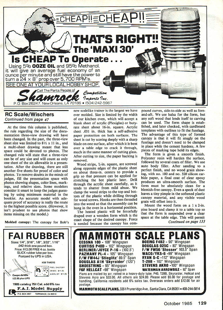
We prefer to fasten the canopy to a finished and painted model using Wilhold R/C-56 glue, because it adheres well to smooth surfaces, retains rubberlike properties, and dries clear. Spread a narrow band, 1/16 to 1/8 in. wide, along the canopy edges and lay it carefully in place, using small scraps of masking tape to hold the edges. At this point, it becomes apparent that a perfectly fitted canopy made from a mold is a tremendous advantage. An ill-fitting canopy can be a real headache when trying to glue it on the fuselage. R/C-56 dries quite slowly because it is trapped between plastic and paint. Of course, all cabin details, instrument panels and dummy pilot must already be in place.
We use small, vacuum-formed clear plastic scoop vents in the lower corners of the canopy to ventilate its interior. Without adequate ventilation, water will condense on the inside whenever the model is exposed to sunlight. The vents also serve to relieve pressure inside from the sun's heat, which could blow a sealed canopy off the fuselage. With a large canopy flown at high speed, considerable lift is developed over its upper surface, and we have seen some of ours depart suddenly from the airplane. Holes for ventilation must be made in the canopy before fastening to the model. We have tried to do this afterward and have found the bits of plastic stuck to the canopy interior by static attraction. They are permanently attached. Glue joints are covered with paint to match the fuselage color.
Panel lines
A letter requested information about application of panel lines on models using a pen-and-ink method. Black India ink lines drawn with a draftsman's ruling pen are too contrasty to look realistic. They tend to appear in exaggerated boldness on light-colored surfaces. On dark colors, even the intense black of India ink isn't easily seen. The advantage of ink is ease of application, especially with ink that is intended for drawings on drafting mylar film. An example of this type is Koh-I-Noor Rapid-O-ink for film. It is waterproof and less likely to chip off, but a final protective coat of clear epoxy would be recommended. Less conspicuous and more realistic are lines in other colors, such as gray. Paint must be quite thin to be applied with a ruling pen. Floquil model railroad paint is thin as it comes from the bottle and probably would need little thinning. It is fuel proof, adheres well, and may need no overcoating with epoxy.
Use of a ruling pen may need explanation. The pen has an adjustment screw to regulate line width. Ink or paint is placed between the pen's nibs with an applicator, which is in the cap of the ink bottle. When using paint, add it between the nibs with a toothpick. Either ink or paint must be applied on the model quickly, as it will dry at the pen tip and then refuse to flow. When this happens, it can sometimes be urged to flow by squeezing the nibs together with your fingers to break the solidifying liquid at the tip.
Another method of adding panel lines is with very narrow strips of self-adhesive tape beneath the paint. This produces a panel line that stands slightly above the surrounding surface and is quite easily seen from a distance. Viewed from close up, it seems exaggerated. The tape can be as narrow as .015 to .030 in. and is normally used for laying out printed circuit boards in the design stage. It is found in drafting supply houses. Heavy paint over these strips will tend to disguise their edges.
Our preferred method for panel lines is with heavy primer applied along a strip of masking tape. When dry, the tape is removed and the primer sanded or rubbed down to produce a fine, realistic panel line which may be further refined by scribing if desired. After drying, the primer is sanded down to the tape level and feathered into the adjacent area. When the tape is removed, the line edge of remaining primer stands above the model surface by the amount of tape thickness. For more pronounced lines, use double layers of tape. Heavy paint buildup over these lines tends to hide them and, therefore, only light coats should be added.
Bob and Dolly Wischer S-221 Lapham Peak Rd., Delafield, WI 53018.
Transcribed from original scans by AI. Minor OCR errors may remain.

