
Radio Control: Scale
Bob and Dolly Wischer
FAI rules
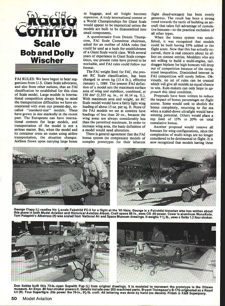
We have begun to hear suggestions from U.S. Giant Scale advocates, and also from other nations, that an FAI classification be established for this class of scale model. Large models in international competition always bring to mind the transportation difficulties we have encountered with even our present-day, so-called "standard-size" models. These have grown in size markedly in the recent past. The Europeans can have international contests for large models, and transportation of the model is not a serious matter. But, when the model and its container cross an ocean using airline transportation, the situation changes. Airlines frown upon carrying large boxes as baggage, and air freight becomes expensive. A truly international contest or a World Championships for Giant Scale would appear to be impractical unless the models are built to be disassembled into small components.
A questionnaire from Dennis Thumpston, FAI Scale Committee chairman, asked for an outline of AMA rules that could be used as a basis for establishment of a Giant Scale world class. With several years of experience in Giant Scale competition, our present rules have proved to be workable, and FAI rules could follow our format.
The FAI weight limit for F4C, the present RC Scale classification, has been changed to 7 kg (15.4 lb), effective January 1, 1989. The present FAI definition of a model sets the maximum surface area of wing and stabilizer, combined, at 150 dm² (2,325 sq in, or 16.14 sq ft). With maximum area and weight, an RC Scale model would have a fairly light wing loading of about 15 oz per sq ft. None of the FAI models we see at contests have loadings of less than 20 oz per sq ft, because the wing areas are always considerably less than the permitted maximum. In order to increase wing area, the basic definition of a model would need alteration.
There is general agreement that the FAI bonus system (to compensate models of complex prototypes for their inherent flight disadvantages) has been overly generous. The result has been a strong trend towards the tactic of building an aircraft that takes full advantage of cumulative bonuses—to the practical exclusion of all other types.
When the bonus system was established, it was recognized that models could be built having 35% added to the flight score. Now that this has actually occurred, there is real concern about its effect on contest entries. Modelers who are not willing to build a multi-engine, taildragger biplane for high bonuses will drop out of competition because of the recognized inequalities. Diminished interest in FAI competition will surely follow. Obviously, no set of rules can be created which will give all models an equal chance to win. Rule-makers can only hope to approach this ideal condition.
Proposals have been written to reduce the impact of bonus percentages on flight scores. Some would seek to abolish the bonus completely, returning to the era when a scaled-down ultralight would have winning potential. Others would place a top limit of 15% to 20% on total cumulative bonuses. Another proposal would remove all bonuses for wing configurations, since the complexities of multi-wings are no longer considered detrimental to flight. It is now recognized that models having three or more engines are actually less hazardous to fly than twins, and this is the basis for reducing the multi-engine bonus to 10%, regardless of number. These proposals will come to a vote in the April 1986 FAI session in Paris. Should they be accepted, the effective date for rule change will be January 1989. Have an opinion? Let's hear it.
Design aid
Enlarging drawings from small three-views is made easier by using a circular slide rule intended specifically for the purpose. Shelby Hagberg uses the C-Thru PS 80 Proportional Scale. It is a pair of 8-in.-diameter plastic discs, mounted concentrically, and graduated from 1 to 100 inches. The upper disc is rotated over the lower. The upper disc has a window for setting the scale ratio between the three-view drawing and the size of model desired. Once set to the proper ratio, all dimensions are read along the periphery of the discs without having to reset.
For dimensions less than one inch on the three-view drawing, it is necessary to convert the fraction to decimals, using a decimal equivalent chart. For example, 1/2 becomes .50 on the inner disc by placing a decimal point before the five (or .50 inch) graduations. The desired dimension can then be read on the outer scale as either a fraction or converted to decimals.
Our preference for enlarging a three-view would be to use an electronic calculator set to a constant multiplication factor, and then use a decimal-inch ruler—one that is graduated in increments of 1/50 (.02 in.)—to transfer dimensions from the three-view to the enlarged drawing. However, we recognize that not everyone is adept with the decimal-inch system which has been U.S. industry standard for the past quarter-century. The C-Thru Proportional Scale is for those who prefer working in fractions.
When we purchase balsa at the local hobby shop, it is dimensioned in fractions, as are many other hobby items, such as music wire. It seems that we U.S. modelers will be forever stuck with our clumsy dual-dimensioning systems of fractions and decimals, with metric lurking in the background to further confuse our thinking. Those who have been exposed to FAI competition have learned to live with metrication. It must be agreed that it is much easier to calculate in metric dimensions. Shelby obtained his Proportional Scale at an art store. Price was about $4 for one having an 8-in.-diameter scale, and $2.50 for a 6-in. one.
Airfoil handbook
In our September 1985 column, there was mention of the Handbook of Airfoil Sections for Light Aircraft by Michael S. Rice. A reader asked about a source for the book. It is currently being advertised in the pages of Model Aviation by Zenith Aviation Books. The price is $8.95, and the catalog number is 106401B.
The book contains about 125 airfoils from the U.S., Belgium, England, France, Germany, and Italy. Included are the Boeing, Clark, NACA, RAF, Eiffel, and Goettingen series. Each airfoil is shown in cross section with coordinates at various percentages of wing chord. Curves are also given for ratio of lift to drag, center of pressure travel, lift coefficient, and drag coefficient. Modern jet-aircraft-type airfoils are not included.
For the scale modeler interested in reproducing the exact airfoil used on the prototype, the airfoil curves can be plotted above and below the mean chord line for semi-symmetrical sections. The shape is described in percent of chord at points along the chord. A simple calculator makes short work of the mathematics, even for a tapered wing. The 16 ribs of our Ryan SCW's wing (NACA 23012 airfoil) were plotted from information in the book.
Having seen any number of scale models flown successfully with non-scale airfoils, we would agree that exactness in airfoil sections is not an absolute necessity. There is some personal satisfaction in knowing that the airfoil used on the model is in agreement with the prototype. We have never found a scale airfoil to be detrimental to performance.
A thick airfoil, particularly near the wing tips, spoils scale appearance, but this feature may have some benefit in achieving acceptable scale speed by increasing drag. "Eyeball" airfoils, some having fully symmetrical sections, are quite common, and the models fly well. The number of purists who demand scale appearance and performance is low, when compared to the total of scale modelers.
Custom fuel tanks
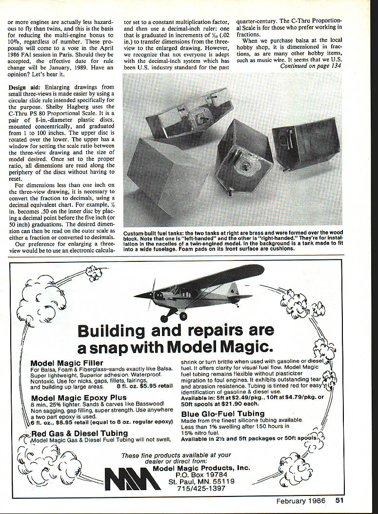
The available space in a scale model doesn't always fit the shape of ready-made fuel tanks. We have been forced to accept the inevitable task of producing custom tanks for more than half of our models. One advantage of a custom tank is that it assures maximum capacity within the space available. Using a soft-wall tank has saved my fingers many times in installing tanks in tight spaces, and a seam-welded tank is often too large to be squeezed into the tank bay.
For some models I have made tanks by making a thin fiberglass shell over a wax or soap "buck" with the internal fuel connections glued to the outside of the buck; the shell is then removed and sealed. Another method is to hand-bend thin brass, solder the seams, and solder on tubing fittings. I've used forward and aft filler and vent fittings to assure complete filling in minimum space. Our preferred material is .005 in. brass or copper sheet with a 1/4-in. OD brass tube for fuel fittings.
A flexible silicone fuel pickup tube is permanently sealed inside the tank with a weight at the free end, as in a plastic "klunk" tank. The hardness of brass sheet varies from soft annealed to hard shim stock, which is the most expensive. Half-hard tempered brass sheet thickness is .006 in., minimum. Soft annealed brass, .005 in. thick, is suitable for tanks, but it dents easily, as does soft copper. The clunk inside of the silicone tube end has enough mass to cause dents in annealed materials.
Our oldest brass tank is semi-permanently sealed inside an Emeraud, built in 1971. The silicone tube and its attached weight can be heard as it rattles around inside, and there has been no problem with fuel feed. It must be pointed out that a metal tank should be completely emptied of fuel after every flying session to avoid internal corrosion. Of course, we also do this with plastic tanks.
The tank is shaped with a V-bottom to be certain that it can be completely emptied. This also helps to keep the weighted pickup tube centered so that it will use the last bit of fuel at the end of a long flight. The V-bottom is only slightly more difficult to form than a flat bottom.
Some of our tanks are formed around a wood block, shaped like an inverted house. The brass sheet is then wrapped around the block, allowing an extra 1/8 in. of material for the solder joint at one corner. The ends are also formed around the block, allowing 1/8 to 1/4 in. for soldering around all edges. With this method, properly fitting ends inside the wraparound sheet are a certainty. Use steel wool to burnish all areas that will be soldered, to assure a flow of melted solder.
A wood form is a convenience, but not a necessity. By sketching an end view of the tank, dimensions can be determined for the length of the wraparound sheet, top, bottom, and sides. The sheet is then formed over a sharp edge, such as a heavy steel ruler. After inserting the formed ends, the tank retains its shape. Tack-solder the material in a few spots to be sure of squareness before soldering all edges.
Lightly coat the areas to be soldered with a good soldering paste such as Nocol-rod, for example, and join the edges with 50-50 solder (50% lead, 50% tin). The paste provides instant flow of solder on the metal. Tight-fitting joints need only a small amount of solder for less weight. A brass tank made from .005-in. material will weigh less than one made from high-density polyethylene.
We use a tapered steel scriber to punch holes for tubes. This should be done with care to avoid an oversize hole. A slight press fit on the 1/8-in. diameter tube is desirable, and this is quite easily achieved by pushing the scriber slowly through the brass. The scriber will flare the brass sheet to increase the contact area for the solder fillet.
On most tanks, there are three tubes: for fuel feed, filling, and venting. The hole for the fuel feed must be larger, in order to pass the internal silicone tube and its clunk weight. A scrap of brass, with a 1/8-in. hole punched near its center, then covers the large hole and is soldered in place after inserting the weighted tube. Brass tubes for fill and vent can be straight or bent to suit the individual installation. For convenience in emptying a tank, a fourth tube can be added at the apex of the V-bottom.
Because almost all engines run more reliably with muffler pressure in the fuel tank, there is a Y-connector, made from soldered brass tube, in the tank vent line. The connector is installed in the silicone tube somewhere near the point where it passes close to the muffler. It follows that the silicone fill and vent tubes must be plugged to retain pressure in the tank. Use a No. 6-32 x 1/4-in. machine screw to plug the line ends. A tube used for emptying the tank should be plugged at all times when not in use.
Custom-building a fuel tank permits all sorts of modifications. Brass strips can be soldered along the tank's edges which fit into groove runners in the fuselage, giving a slide-in assembly. The brass fill tube can have its inner end bent down in close proximity to the V-bottom so that fuel can be pumped out as well as into the tank from the same location. The tank can be made very wide to completely fill the space in a wide fuselage. Aerobatics are not affected by this tank shape. The weighted pick-up tube follows the fuel around inside the tank, regardless of its shape.
The completed tank should be cleaned internally with lacquer thinner to remove solder paste residue. Check for leaks by plugging all but one of the openings. A length of silicone tube placed on the remaining tank tube is used to pressurize the tank by thumb power, and the tank is then submerged in water. Look for bubbles. As an alternative, supply pressure in the same manner and then pinch the tube. Wait a minute or two, then release the tube and listen for the rush of escaping air. Thin brass will balloon slightly when pressurized. If it doesn't stretch, there is a leak.
To determine the size of tank needed, calculate capacity from the formula: one U.S. fluid ounce equals 1.805 cu in. Calculate the square-inch area of one end and multiply by the tank length to find the content in cubic inches. Divide by 1.805 to find the content in fluid ounces. Not enough? Modify the tank dimensions as needed until the capacity equals the need.
Bob and Dolly Wischer S-221 Lapham Peak Rd., Delafield, WI 53018.
Transcribed from original scans by AI. Minor OCR errors may remain.

