
Radio Control: Scale
Bob and Dolly Wischer
Liquid Cooling
Engine cooling on scale models can be a serious problem, particularly when the modeler values engines and searches for ways to extend their lives. A tightly‑cowled engine is vulnerable to excessive wear due to overheating. Adding extra lubricant to the fuel can help avoid wear but introduces another variable and a possibility it may be forgotten if the model isn’t flown often. A reader requested information about liquid cooling of tightly‑cowled engines.
Almost every prototype that has liquid‑cooled engines—examples are WWII fighters and aircraft with pusher propellers—presents a problem to the scale modeler because there may be no suitably large openings for ventilation. The obvious alternative is to use non‑scale openings for ventilation, but these are unsightly to a scale purist.
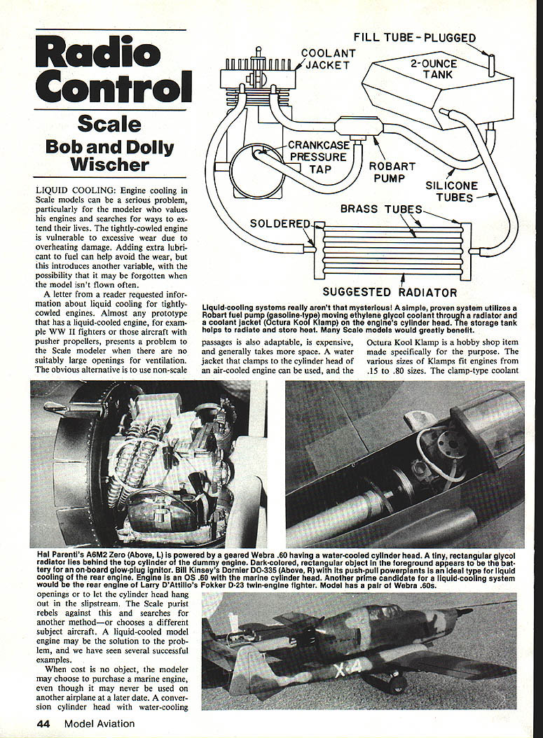
Liquid‑cooling systems really aren’t mysterious. A simple, proven system uses a Robart gasoline‑type pump to move ethylene glycol coolant through a radiator and a coolant jacket (Octura Kool Klamp) on the engine’s cylinder head. A storage tank helps to radiate and store heat. Many scale models would greatly benefit from such a system.
Coolant jackets and conversions
A water jacket that clamps to the cylinder head of an air‑cooled engine can be used; Octura Kool Klamp is a hobby‑shop item made specifically for this purpose. Various sizes of Klamps fit engines from .15 to .80 sizes. The clamp‑type coolant jacket is also adaptable, though it generally takes more space.
When cost is no object, a modeler may choose to purchase a marine engine or a conversion cylinder head with a water‑cooling jacket fastened to the cylinder head. This will carry away the greatest part of the heat. In airplane use the clamp jacket acts as a combination air/glycol cooling arrangement.
Ethylene glycol (automotive antifreeze) is the recommended coolant. It is a better heat‑carrying medium than water, expands less with temperature rise, has a higher boiling point, and is less corrosive.
Pump and plumbing
The glycol is circulated through the Kool Klamp by a Robart pump of the type used with gasoline and diesel fuels. This pump employs pulsating crankcase pressure as the driving force. The engine’s crankcase must be tapped for a pressure fitting. The Robart pump isolates the coolant from the engine, so there is no possibility of contaminating the engine with glycol.
A glycol storage tank is preferably located where a stream of cooling air can be directed over it. If the tank is made sufficiently large it becomes a heat‑storage tank and, for short flights with long cooling periods between flights, no other radiator may be needed. However, a large tank filled with glycol adds considerable weight to an already heavy scale model. A six‑ or eight‑ounce tank located far forward in the nose may help correct a tail‑heavy model. Pump placement within the fuselage or nacelle must allow adequate circulation; with the Robart pump, the tank can be at some remote location.
Radiators and placement
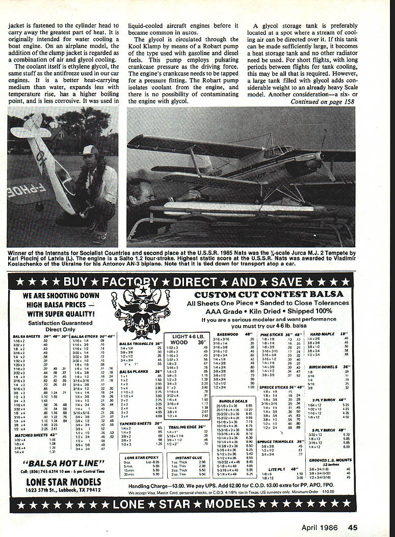
The most desirable alternative in most cases is some sort of radiator to transfer engine heat to outside air. A liquid‑cooled system is ideal because the radiator can be located wherever air flows. Rapid transfer of heat means a minimum of fluid is carried in the system; long connecting tubes become part of the radiator. This is analogous to the large air scoop on the rear belly of a Mustang or the nose inlet of a Corsair, and in models a smaller intake often suffices.
Glycol is pumped out of the tank, through the Kool Klamp, through the radiator, and back to the tank. Radiators should be placed where cooling air will pass through them; for radial‑engine models, the radiator can be mounted in the lower portion of the cowl with a small opening between dummy cylinders to admit air and an exhaust at the cowl’s rear.
When the radiator or storage tank is remotely located (for example, in the belly of a Mustang), aluminum tubes running through the fuselage can become a substantial part of the radiating system. In some installations a two‑ounce brass or tinplate tank mounted in moving air from prop or slipstream can be sufficient.
Radiator construction options
- Strip‑type radiators: Easily made from brass and soldered or brazed to create many small passages.
- Model boat heat exchangers: Compact and adequate for small engines; sold commercially for model boats.
- Fan‑assisted radiators: Used where airflow is limited; fans may be driven by an electric motor or by a belt from the engine.
- Helical coils: Three‑foot lengths of brass or aluminum tubing can be shaped into a helical coil. Anneal the tube before attempting small‑radius bends. Use a tube bender (a tightly wound helical spring slipped over the tube) to prevent kinking.
- Tubing diameters: 1/8", 5/32", or 3/16".
- A slight flattening at bends is acceptable; coolant velocity increases through restricted sections.
- Suggested minimum tube lengths by engine size: about 12" for a .40 engine and 16" for a .60 engine; increase length for more restricted airflow.
- Header/tube construction: Solder a row of tubes into headers like automotive radiators; headers can be brass blocks or larger tubes.
- Serpentine coils: Connect several lengths of tube with plastic fuel tubing at their ends to form an elongated serpentine coil—avoids bending metal.
- Plate radiator: Thin annealed brass plates with depressed passages soldered together to form a serpentine duct. Small and efficient examples have been made for .60 engines.
Air removal and sealing
- Use silicone tubing and properly sealed fittings.
- Check for leaks by pressurizing the system with air and submerging in water or by using a leak‑detecting spray.
- Keep the system free of contaminants; flush with distilled water before adding ethylene glycol.
- Remove air from the system. If there is no circulation (no heat in the storage tank or a cold radiator), suspect an air bubble—especially in the pump. A fuel bulb helps evacuate air; suction often works better than pressure.
- Plan for drain and fill provisions and mount the filler where it can be reached easily. Protect the coolant from excessive heat and prevent spills on the aircraft finish.
Practical considerations
Liquid cooling is not for the casual modeler, but it offers solutions where air cooling is impractical. With careful installation and testing, a glycol‑based system can extend engine life and improve reliability for tightly‑cowled scale models.
We have seen models with inadequately cooled engines that were barely airborne because of overheating and sagging output. Such engines can be damaged by heat even if they run adequately on cool days. Glycol cooling can be a great engine saver, especially for modelers who value their equipment.
Modeling Tools
Special tools introduced to the workshop are now indispensable.
- Needle files:
- Coarse, sharp, wood‑rasp‑type needle files (Gyros brand) make short work of tough wood without loading up like standard files.
- Metalworking needle files, four inches long with extra‑fine teeth, are ideal for manipulation in confined spaces.
- Tiny steel mechanic’s squares: Two, three, and four‑inch sizes (made in England) are useful for squaring ribs and holding parts in alignment until glue sets.
- K & S tubing cutter: Trims brass or aluminum tube cleanly, leaving an absolutely square end for tubes from 1/16" to 1/2". Follow up with a needle file to remove burrs.
- Screw Sticker: A three‑inch spring‑loaded device that grips the head of small screws securely (useful for tiny 00‑90 screws).
- Hex‑head screw tools: Use appropriate K & S drivers or small hex tools for sizes 00‑90, 0‑80, 1‑72, 2‑56, and 3‑48.
These tools simplify many of the small tasks involved in building and installing liquid‑cooling systems and other scale model work.
Transcribed from original scans by AI. Minor OCR errors may remain.

