
Radio Control: Scale
Bob and Dolly Wischer
Design Your Own
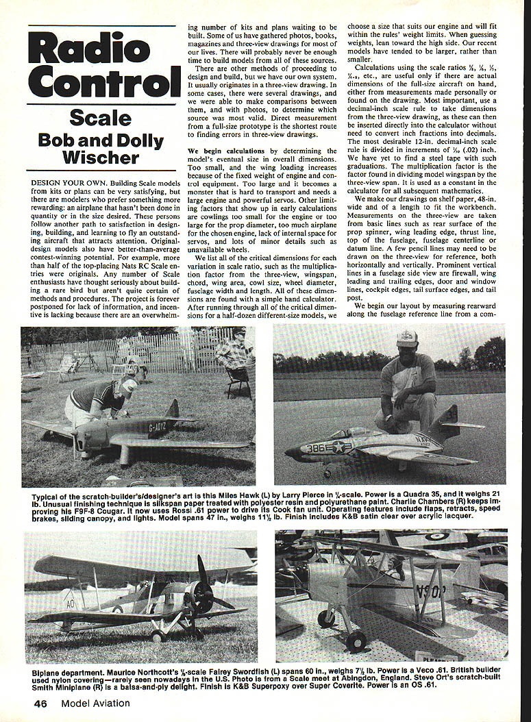
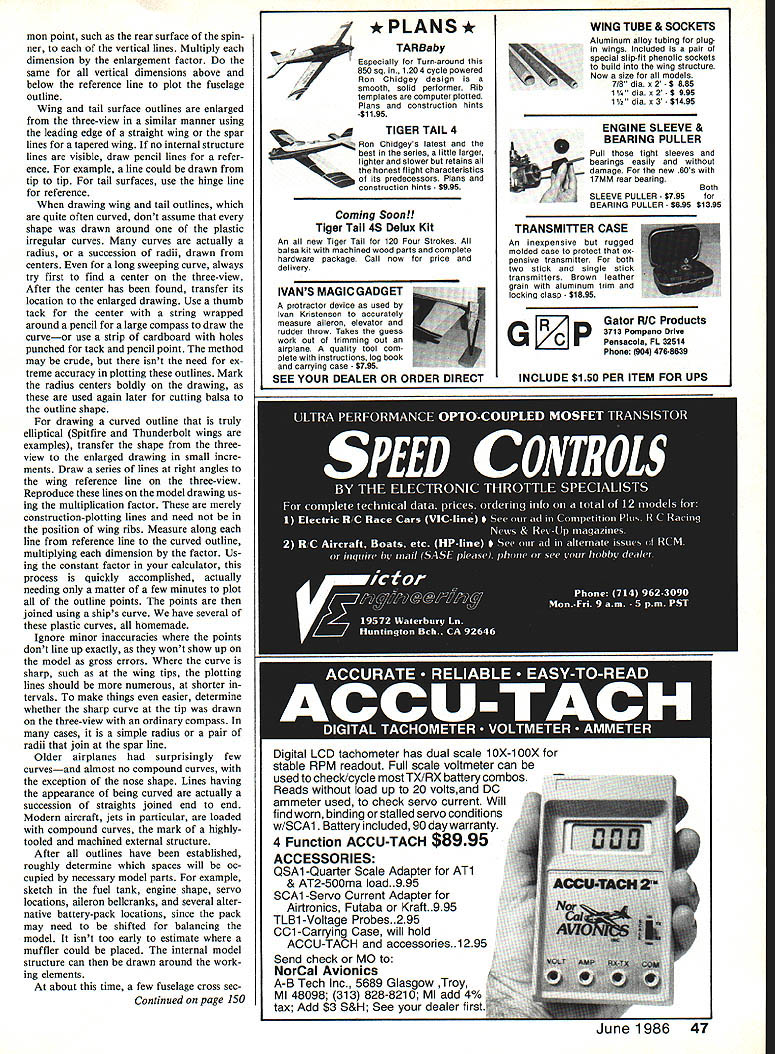
Building scale models from kits or plans can be very satisfying, but some modelers prefer something more rewarding: an airplane that hasn't been done in quantity or in the size desired. These persons follow another path to satisfaction in designing, building, and learning to fly an outstanding aircraft that attracts attention. Original-design models also have better-than-average contest-winning potential. For example, more than half of the top-placing Nats RC Scale entries were originals.
Many scale enthusiasts have thought seriously about building a rare bird but aren't certain of methods and procedures. The project is often postponed for lack of information or incentive, because there are so many kits and plans waiting to be built. Some of us have gathered photos, books, magazines, and three-view drawings for most of our lives. There will probably never be enough time to build models from all of these sources, but there are other methods of proceeding to design and build. We use a system that usually originates with a three-view drawing. In some cases several drawings are available, allowing comparison with photos to determine the most valid source. Direct measurement from a full-size prototype is the shortest route to finding errors in three-view drawings.
Choosing Scale and Initial Calculations
We begin calculations by determining the model's eventual overall dimensions. Too small, and wing loading increases because of the fixed weight of engine and control equipment. Too large, and it becomes difficult to transport and needs a large engine and powerful servos. Other limiting factors that show up in early calculations are cowlings too small for the engine or too large for the chosen engine, lack of internal space for servos, and minor details such as unavailable wheels.
We list all critical dimensions for each variation in scale ratio (for example 1/2, 1/3, 1/4). Typical critical dimensions include:
- wingspan
- chord
- wing area
- cowl size
- wheel diameter
- fuselage width and length
All of these dimensions are calculated with a simple hand calculator. After running through the critical dimensions for a half-dozen different-size models, we choose a size that suits our engine and will fit within the rules' weight limits. When guessing weights, lean toward the high side. Our recent models have tended to be larger rather than smaller.
Calculations using scale ratios such as 1/2, 1/3, 1/4 are useful only if actual full-size dimensions are on hand, either from personal measurements or found on the drawing. Most important, use a decimal-inch scale rule to take dimensions from the three-view drawing so the values can be entered directly into the calculator without converting inch fractions to decimals. The most desirable 12-in. decimal-inch scale rule is divided in increments of 1/50 (0.02 in.). We have yet to find a steel tape with such graduations. The multiplication factor is the factor found by dividing model wingspan by the three-view span; it is used as a constant in the calculator for subsequent mathematics.
Drawing and Enlarging the Three-View
We make our drawings on shelf paper, 48 in. wide and a length to fit the workbench. Measurements on the three-view are taken from basic reference lines such as rear surface, spinner, wing leading edge, thrust line, top fuselage, and fuselage centerline datum. A few pencil lines may need to be drawn on the three-view for reference, both horizontally and vertically.
Prominent vertical lines in fuselage side views include firewall, wing leading and trailing edges, door and window lines, cockpit edges, tail surface edges, and tail post. Begin layout by measuring rearward along the fuselage reference line from a common point such as rear surface, spinner, or a vertical line. Multiply the dimension by the enlargement factor. The same vertical dimensions above and below the reference line are plotted and the fuselage outline is drawn. Wing and tail surface outlines are enlarged from the three-view in a similar manner using leading-edge and straight wing-spar lines.
For a tapered wing with no internal structure lines visible, draw pencil lines for reference (for example, a line from tip to tip). For tail surfaces, use the hinge line for reference.
When drawing wing and tail outlines, which are often curved, don't assume every shape was drawn with a plastic irregular curve. Many curves are actually a radius, or a succession of radii, drawn from centers. Even for a long sweeping curve, try first to find a center on the three-view. After the center has been found, transfer its location to the enlarged drawing. Use a thumbtack for the center with a string wrapped around a pencil as a large compass to draw the curve—or use a strip of cardboard with holes punched for tack and pencil point. The method may be crude, but extreme accuracy is not required for these outlines. Mark the radius centers boldly on the drawing, as these are used later for cutting balsa to the outline shape.
For curves that are truly elliptical (Spitfire and Thunderbolt wings are examples), transfer the shape from the three-view to the enlarged drawing in small increments. Draw a series of lines at right angles to the wing reference line on the three-view. Reproduce these lines on the model drawing using the multiplication factor. These are merely construction-plotting lines and need not coincide with wing-rib positions. Measure along each line from the reference line to the curved outline, multiplying each dimension by the factor. Using the constant factor in your calculator, this process is quickly accomplished, taking only a few minutes to plot all outline points. Join the points using a ship's curve. We have several of these plastic curves, all homemade.
Ignore minor inaccuracies where the points don't line up exactly, as they won't show up on the model as gross errors. Where the curve is long, such as at the wing tips, plotting lines should be more numerous and at shorter intervals. To make things even easier, determine whether the sharp curve at the tip was drawn on the three-view with an ordinary compass. In many cases it is a simple radius or a pair of radii that join at the spar line.
Older airplanes had surprisingly few curves—and almost no compound curves, with the exception of the nose shape. Lines that appear curved are often a succession of straight segments joined end to end. Modern aircraft, jets in particular, are loaded with compound curves—the mark of a highly tooled and machined external structure.
Internal Layout and Structure
After all outlines have been established, roughly determine which spaces will be occupied by necessary model parts. Sketch in the fuel tank, engine, shaft, servo locations, aileron bellcranks, and several alternative battery-pack locations, since the pack may need to be shifted for balancing the model. It isn't too early to estimate where a muffler could be placed. The internal model structure can then be drawn around the working elements.
At about this time, sketch a few fuselage cross sections to be certain all parts will fit across the fuselage width. Plot the section shapes in the same manner as other curves from the three-view. Important bulkheads are:
- the firewall (plywood)
- an engine-mounting bulkhead
- a bulkhead at the wing leading edge (preferably plywood)
- a load-carrying member at the wing trailing edge
The greatest trouble source in model design is a built-in overweight condition. Adding structure and using heavier materials than necessary can produce a model that must fly fast to become airborne, with resulting control problems. Concentrate weight at points needing extra strength—where hard materials meet balsa. The engine mount commonly used in scale models is aluminum, fastened to a plywood firewall. The ply is epoxy-glued to the balsa frame with large-area balsa gussets.
Landing gears also require special attention. Where steel connects to a balsa structure, intermediate parts of hardwood or ply will spread landing-shock loads. Tires alone shouldn't be depended upon to absorb shock. A gear with springs is preferred. Telescoping struts with internal springs, sometimes used on full-size aircraft, preserve scale appearance and function. Fastening such members into a wing or fuselage demands that the load be spread over an area. The strut should be set into a hardwood block, which is then anchored to adjacent structure with steel bolts. Glue alone will not withstand repeated landing shock. A music-wire gear that will endure an unlimited number of landings should be tied into ply with steel straps and machine screws. This is necessary weight—avoid adding weight where lesser weight will suffice.
Construction Techniques and Resources
Construction technique information can be found by examining magazine drawings and kits. A modeler designing his own scale aircraft for the first time should have previous experience with kits or scratch-building. In our design efforts, we shamelessly borrow construction ideas from everyone and assume that others do likewise. Internal structure, use of formers for wings, and step-by-step construction procedures have been detailed in model magazines. When a modeler does his own designing, truly innovative ideas begin to materialize, and there is real satisfaction. None of us knew our capabilities until we made that first bold step into model design.
Hobbypoxy Colors
Pettit Paint Co., maker of Hobbypoxy products, has published a series of formulas over the past several years showing how to mix the various shades used on military aircraft of nations involved in WWII. The latest, and probably the last of the series, is for German Luftwaffe insignia and marking colors.
The cross and swastika insignia were black and white, for which standard Hobbypoxy H81 Black and H10 White may be used. Note, however, that the insignia were painted in a semi-gloss finish, which produced a slight sheen. Hobbypoxy suggests using a combination of gloss hardener and flat hardener—about a 50:50 mix—to produce this effect. Registration and unit-code markings were flat finish; the most common colors being black, white, red, yellow, and blue.
The formulas presented here are for Luftwaffe colors 04 Yellow, 23 Red, and 24 Dark Blue:
- Yellow 04 — 40 parts H49 Cub Yellow, 2 parts H70 Gray, 1 part H58 Bright Red
- Red 23 — 22 parts H65 Bright Red, 2 parts H66 Dark Red, 1 part H47 Bright Yellow, 1 part H10 White
- Dark Blue 24 — 3 parts H43 Dark Blue, 5 parts H65 Bright Red, 1 part H10 White
Bob and Dolly Wischer S-221 Lapham Peak Rd., Delafield, WI 53018
Transcribed from original scans by AI. Minor OCR errors may remain.

