
Radio Control: Scale
Bob and Dolly Wischer
Fact or Fiction?
One of the fictional theories about model flying is the importance of scale effect — our bugaboo of the past that supposedly kept a model from flying in a manner similar to its prototype. We have been asked whether scale effect makes changes necessary in airfoils or tail surface areas. Our answer is that present-day RC scale models don't need these changes.
Scale effect can be a factor on very small, light, and slow-flying models such as Peanut Scale, rubber-powered, or Schoolyard Scale RC types. However, in the sizes now flying with .40, .60, or 1.20 engines, the effect isn't evident. This is accentuated in our experience when we compare flights of our models with those of their full-size counterparts and find remarkable similarities. Giant scale models are even more like their prototypes.
Early practice and tail surfaces
In the distant past, scale models were often given enlarged tail surfaces because of expected instability problems. None of our existing scale models have non-scale control surface areas. World War I aircraft models may have been at the root of some horror stories about the need for increased area.
Examples:
- The Morane-Saulnier parasol monoplane had a minuscule elevator and no stabilizer, giving it an evil reputation for being tricky and sensitive in flight.
- In contrast, the Sopwith Strutter had a stabilizer/elevator combination of enormous area, making three-point landings difficult.
Flutter and control-surface problems
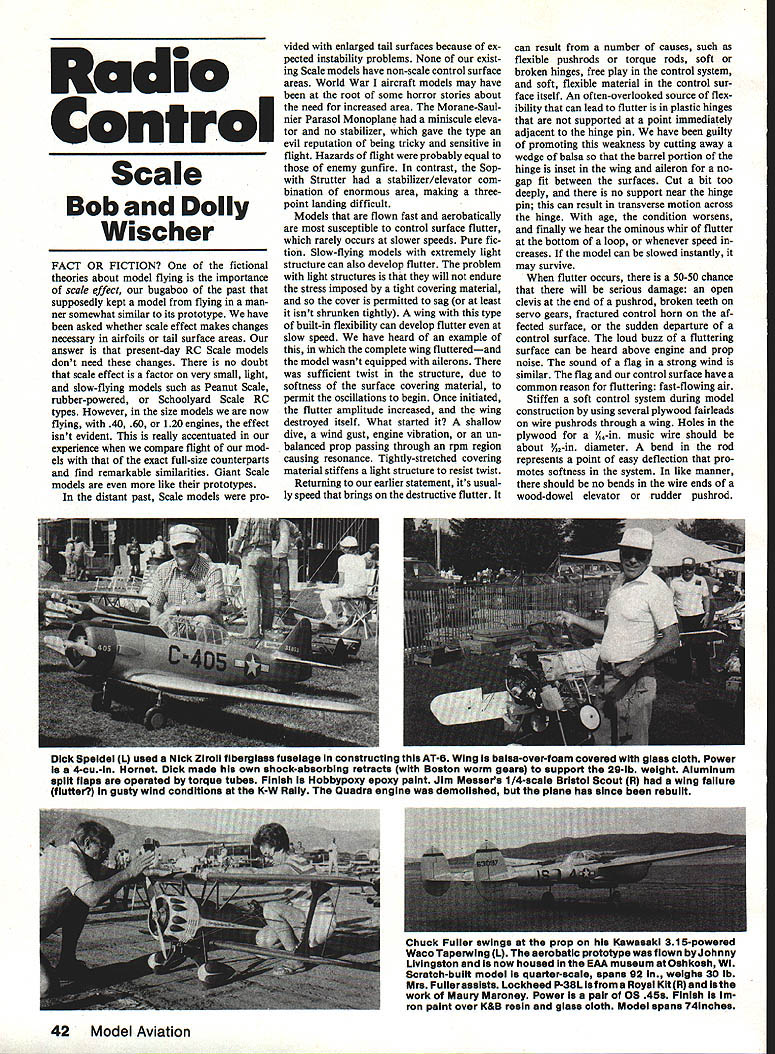
Models that are flown fast and aerobatically are most susceptible to control-surface flutter; this rarely occurs at slower speeds. Slow-flying models with extremely light structure can also develop flutter. The problem with light structures is that they will not endure the stress imposed by a tight covering material, so the cover may be permitted to sag (or at least not be shrunken tightly). A wing with this type of built-in flexibility can develop flutter even at slow speed.
We have heard of an example in which the complete wing fluttered — and the model wasn't equipped with ailerons. There was sufficient twist in the structure, due to softness of the surface covering material, to permit oscillations to begin. Once initiated, the flutter amplitude increased, and the wing destroyed itself. What started it? A shallow dive, a wind gust, engine vibration, or an unbalanced prop passing through an rpm region causing resonance. Tightly stretched covering material stiffens a light structure to resist twist.
Returning to our earlier statement, it's usually speed that brings on destructive flutter. It can result from a number of causes:
- Flexible pushrods or torque rods
- Soft or broken hinges
- Free play in the control system
- Soft, flexible material in the control surface itself
An often-overlooked source of flexibility that can lead to flutter is plastic hinges that are not supported immediately adjacent to the hinge pin. We have been guilty of cutting away a wedge of balsa so that the barrel portion of the hinge is inset in the wing and aileron for a no-gap fit. Cut too deeply and there is no support near the hinge pin; this can result in transverse motion across the hinge. As the condition worsens, you may hear the ominous whir of flutter at the bottom of a loop or whenever speed increases. If the model can be slowed instantly, it may survive.
When flutter occurs, there is a 50–50 chance of serious damage: an open crash at the end of a pushrod, broken teeth on servo gears, a fractured control horn on the affected surface, or the sudden loss of a control surface. The loud buzz of a fluttering surface can be heard above engine and prop noise; the sound is similar to a flag in a strong wind. The flag and a control surface have a common reason for fluttering: fast-flowing air.
Stiffen the control system
Stiffen a soft control system during construction:
- Use several plywood fairleads or wire pushrods through wing holes.
- Use 3/32-in. music-wire pushrods where appropriate. Avoid bends in the rod; a bend is a point of easy deflection and promotes softness.
- Ensure there are no bends in the wire ends of a wood-dowel elevator or rudder pushrod.
- Avoid long wire torque rods to operate ailerons; these invite aileron flutter. For the average .60-size airplane, a wire longer than four inches should be 1/4-in. music wire rather than 3/32-in.
- Even better: use a 3/16-in. O.D. aluminum tube with 3/16-in. birch dowel end-inserts epoxied and pinned in each end to resist twist.
Bits and pieces
Threading music wire
Fiction: music wire is too tough to be threaded. Fact: it can be done, with care.
Die sizes:
- 1/8-in. music wire — use a No. 5-40 die
- 3/32-in. music wire — use a No. 8-32 die
- 3/64-in. music wire — use a No. 10-32 die
Technique:
- Chamfer the wire end for an easy start.
- Use a good threading lubricant (we use Moly-Dex tapping fluid).
- Make only one full revolution of the die, then back off to relubricate.
- On the second pass, cut only a half revolution and back off.
- After that, cut the thread in 1/4-turn increments, always backing off the die to clear chips.
- Work slowly and cautiously to prevent damage to the die and wire.
A threaded end of music wire provides an extra-strong method of fastening two wires at landing-gear junctions in a prototypical manner.
Brazing, heat treatment, and soldering
Music wire can be brazed, but heating to red heat alters its temper: it is no longer “music” wire. If the brazed joint is subjected to bending stress, the wire is no better than ordinary cold-rolled steel and will bend easily. Heat treatment and quenching to restore spring properties are beyond most modelers' capabilities. Attempts to harden music wire by heating and quenching have resulted in brittle, glass-like failure.
When a joint must be strong in bending resistance, consider soft solder over a greater area with a brass or steel tube over the wire to spread the load. With enough wetted solder area along the music wire, a joint of reasonable strength can be made.
Myths disproven at Le Bourget
A couple of RC scale myths were disproven at the Le Bourget Scale World Championships:
- Loss of radio control on metal airplanes is a fiction, at least with modern radio equipment. The winning de Havilland Drover was completely aluminum-covered over a balsa base; its antenna was routed outside during flights.
- Undercambered airfoils are not inherently difficult to control. The second-place Avro 504K, which had an undercambered wing, was absolutely stable in the air (calm wind during its flights helped). The scoring bonus for an undercambered airfoil is now a debatable subject in FAI rules.
The real reason for problems with undercambered wings is structural weakness; the same is true of very thin biplane wings. Shallow spars should be made from hardwood, and wire interstrut bracing becomes truly functional.
Muffler pressure and fuel-tank pressurization
Reliable muffler pressure to the fuel tank is necessary for reducing changes in fuel flow as the tank goes from full to empty. We have used a silicone rubber tube for pressurizing tanks; the tube is plugged after filling to seal against pressure loss. The plug we prefer is a machine screw.
Notes and recommendations:
- Too coarse a thread on the filler tends to tear out the filler in the tank; use a brass or aluminum insert.
- We used fine-thread screws, inserted full-length so the screw head sealed against the tube end, which was cut exactly square.
- Muffler pressure can be great enough to push the screw partly out of the tube, causing pressure leaks and variations in fuel flow that can make the engine sag between flights. On hot days the screw can be blown out entirely.
- Remedy: use a larger-diameter screw for the plug, even though it is not as easily inserted or removed. It saves unnecessary needle-valve tweaking before each flight.
Our philosophy on the needle valve is to set it and then forget it. If the setting changes, look for other reasons in the fuel system (a plugged filter, for example).
Scale documentation source
There have been drawings and articles for scale modelers, products of Robert C. Morrison, for the past 50 years. His Repla-Tech International catalog lists the sort of information modelers seek as scale documentation.
The new 1986 Catalog No. 1 for aircraft includes:
- Three-view drawings of aerobatic aircraft and Reno racers
- Civil and military aircraft drawings by Morrison, Karlstrom, Donaldson, Carter, Aviation News, Hirsch Repla drawings
- MAP scale drawings from England and the complete line of Koku-Fun drawings from Japan
- Scale flying-model plans by Morrison and the MAP line of plans from England
- Color documentation photos from the Repla-Tech collection and photo packs from Scale Model Research by Bob Barka
- Black-and-white photos of late raceplanes, Golden Age raceplanes, Golden Age commercial, military, and civil private aircraft
- A special section with color photos taken at the 1985 Reno races covering Unlimited-class racers, T-6 Texan class, and Formula I class
The catalog is worth the $3 just to know what is available.
Repla-Tech International 48500 McKenzie Hwy. Vida, OR 97488
Bob and Dolly Wischer S-221 Lapham Peak Rd. Delafield, WI 53018
Transcribed from original scans by AI. Minor OCR errors may remain.

