
Radio Control: Scale
Bob and Dolly Wischer
Longitudinal Stability
James M. Ruley, aerospace engineer specializing in aircraft stability and control, Aeronautical Systems Division, USAF, Wright-Patterson AFB, contributed the following discussion on stability theory.
Longitudinal stability is the tendency of an aircraft that has been trimmed to fly at a certain angle of attack (AOA) to return to that AOA when disturbed. For an airplane to be controllable it must have longitudinal stability; therefore it is important to ensure model airplanes are longitudinally stable.
To understand why longitudinal stability is necessary for control, consider what makes an airplane stable. In trimmed flight the total lift (the sum of lift produced by the wing and the horizontal tail) may be considered to act at the center of gravity (CG). Another important point is the aerodynamic center (AC). By definition, the AC is the point at which a change in lift due to a change in AOA will act.
How disturbances affect stability
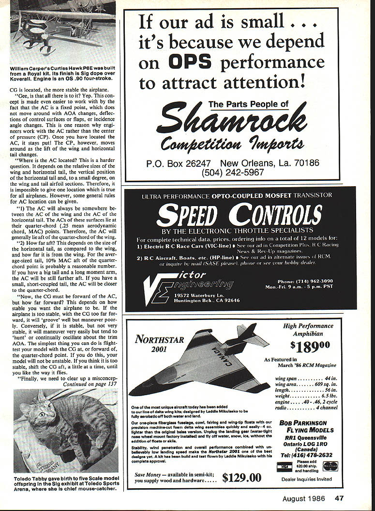
- In a stable case (Figure 1 → Figure 2): if the airplane is disturbed to a higher AOA (for example by an updraft), lift increases. If the AC is behind the CG, the increase in lift produces a nose-down pitching moment about the CG that restores the airplane toward the trimmed AOA. The airplane is longitudinally stable.
- In an unstable case (Figure 3): if the airplane has an aft CG so that the AC is forward of the CG, an increase in AOA produces a nose-up pitching moment that increases AOA further. Small disturbances will diverge, and the pilot must actively fly out of every change in AOA. The airplane is longitudinally unstable.
FACT: Longitudinal stability depends on the distance between the CG and the AC. If the CG is forward of the AC, the airplane is stable. If the CG is behind the AC, the airplane is unstable. The degree of stability is proportional to the distance between the CG and AC—the further forward the CG relative to the AC, the more stable the airplane.
The aerodynamic center (AC)
The AC is useful because it is effectively a fixed point: it does not move with changes in AOA, deflections of control surfaces or flaps, or incidence-angle changes. This is one reason engineers work with the AC rather than the center of pressure (CP). The CP moves as the lift distribution changes; the AC stays put once located.
Where the AC is located depends on:
- the relative sizes of the wing and horizontal tail,
- the vertical position of the horizontal tail relative to the wing,
- and, to a smaller degree, the wing and tail airfoil sections.
Some general rules:
- The AC will always lie between the AC of the wing and the AC of the horizontal tail. The ACs of these surfaces lie at their quarter-chord (0.25 mean aerodynamic chord, MAC) points. Therefore, the overall AC will generally lie aft of the wing quarter-chord.
- How far aft the AC lies depends on tail size and moment arm. For an average tail, about 10% MAC aft of the wing quarter-chord is a reasonable estimate. A larger tail with a long moment arm moves the AC further aft; a small, short-coupled tail places the AC closer to the wing quarter-chord.
Center of gravity (CG) placement
The CG must be forward of the AC for positive stability, but how far forward depends on the desired handling:
- If the CG is too far forward, the airplane will be very stable ("groove" well) but will maneuver poorly.
- If the CG is only slightly forward of the AC, the airplane will maneuver easily but may "hunt" or oscillate about trim.
Practical guidance:
- Flight-test your model with the CG at or slightly forward of the wing quarter-chord. This will prevent instability.
- If the model feels too stable, move the CG aft incrementally until the desired handling is achieved.
Incidence angles and trimming
A common misconception is that relative incidence between wing and stabilizer affects longitudinal stability. It does not—incidence angles set the AOA at which the airplane trims with the elevators neutral, not the stability (which depends on CG vs. AC). Models fly at different AOAs in different flight regimes (fast flight, aerobatics, takeoff/landing), so relative incidence should be chosen to suit the desired trim condition.
Some important cautions:
- Do not use incidence settings on the plans as a reason to move the CG aft until the plane trims with neutral elevators. Doing so may place the CG aft of the AC and make the airplane unstable.
- Instead, set the CG to establish the desired level of longitudinal stability, then use horizontal tail incidence or elevator trim to obtain the desired trim AOA or speed.
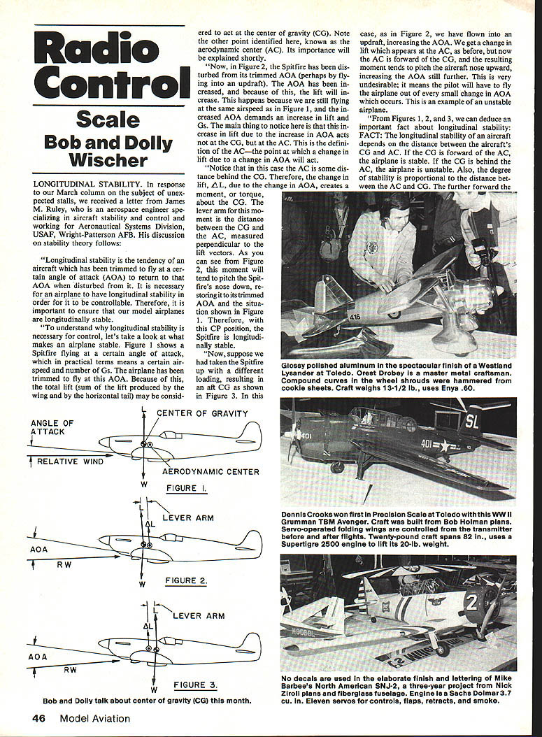
Scale-model concerns and recommended practice
- Scale purists who copy full-size incidence angles exactly can encounter problems. Some full-size aircraft have large wing/stabilizer incidence differences (examples: Taylorcraft, Staggerwing Beechcraft). Large positive wing incidence relative to the stabilizer produces a download on the stabilizer: the wing must lift not only the airplane weight but also counter the stabilizer down-force. That increases required wing lift, shifts the overall AC aft, and requires moving the CG far forward to retain positive stability.
- Balancing such a model at the often-quoted 25–30% of wing chord may not assure safety; the first takeoff can produce a steep initial pull, stall, snap roll, and crash if the modeler is unprepared.
Recommendations:
- If a full-scale prototype has large incidence differences built into the airframe, consider reducing the angular difference to about 2° (many kits use this value) unless you are prepared to set the CG well forward and fly with significant elevator input.
- For models intentionally set up with zero-zero incidence (wing and stabilizer both zero) to produce Pattern-model-type performance: expect neutral longitudinal stability. These models require continuous control input, will not tend to return to level flight on their own, and must be flown like Pattern ships. Many experienced fliers prefer neutral or near-neutral setups, especially those with Pattern experience.
- Current Pattern-flying preferences often favor about 0.5° to 1° wing incidence relative to the stabilizer, with an equal amount of engine downthrust. This helps maintain straight flight without transmitter input during vertical maneuvers when gravity forces are directed toward the tail.
- If the model is built with large fixed incidence differences that cannot easily be changed, be prepared to fly the model with drooped elevators on initial flights until trim is established.
Final practical note: set the CG and incidence sensibly before the first hop. It is easier and safer to establish proper stability by CG placement and then trim the airplane using tail incidence or elevator trim.
Our thanks to James Ruley for this treatise on longitudinal stability. Scale modelers who build from kits or magazine plans normally have incidence angles set appropriately by the designer.
Bob and Dolly Wischer S-221 Lapham Peak Rd. Delafield, WI 53018
Transcribed from original scans by AI. Minor OCR errors may remain.

