

Radio Control: Scale
Bob and Dolly Wischer
Cable systems
The use of cables to operate elevators and rudders is now common on scale models. The real trick in assembling such a system is scale realism: the visible external portions of cables should enter through the fuselage sides at the correct locations, and if elevator cables cross on the prototype, the crossover point should be in the right spot relative to cable length and other external features. This requires some planning.
If possible, study the cable layout and routing on the prototype aircraft. If that information is not available, project the line of each cable on a photo or three-view drawing to help determine the location of the internal bellcrank where the forward ends of the cables are connected. With that information, it is relatively simple to install the model's bellcrank assembly in the proper location.
On full-size aircraft the usual arrangement is a pivot tube across the fuselage with a bellcrank welded to each end and a lever welded near the tube center for connection, by cables or a pushrod, to the control stick. On models, the tube can be replaced by a hardwood dowel with plywood bellcranks cemented near each end. For pivots, drill a .062-in. diameter hole into each end of the dowel, insert short lengths of .062-in. music wire for bearings, and support the outer ends of the wires in plywood bearings drilled for a running fit on the wires. Near the dowel's center cement another plywood lever to connect the pushrod to the servo.
Details of producing a cable-operated system were covered in our December 1985 column; the subject is reviewed here because of a problem discovered on our new Douglas M-2 Mailplane. The M-2 has a pair of cables for each half of the elevator. A visit to the National Air and Space Museum showed that the prototype's cables ran over pulleys at the stabilizer leading edge to give both upper and lower cables equal length so they would maintain tension regardless of elevator position. Such a prominent feature needed to be duplicated on the model.
However, the pulleys introduced four friction points. Standard servos had no trouble overcoming the added friction for full-up and full-down motion, but the problem was evident near neutral. If the transmitter stick was moved a very small amount in the Up direction, the elevator would not return to neutral when the stick was released — too much friction in the system. Tightening the cables excessively made the condition worse.
This produced controllability problems near elevator neutral: continuous hunting in level flight and unpredictable behavior during landing. For example, during a three-point flare the pilot must reduce Up-elevator just before touchdown. If the elevators can't quickly neutralize because of friction, the model can climb, stall, and produce an abrupt landing — possible damage such as a broken prop or, worst, a nose-over.
The solution was to use more energetic servos with fine resolution around neutral. We chose the Ace Atlas servo (assembled from kits). It produces about 45 in.-oz. of torque and uses an amplifier that gives less than a degree of resolution. The motor is relatively large (20 mm diameter) but current drain is not excessive; our regular 550‑mAh batteries are sufficient. With the space available inside most scale models, servo size is not a concern. With higher-resolution servos the elevators now neutralize completely, even when given very small inputs. The model no longer hunts and is far smoother to fly.
Any modeler who remembers older low-resolution servos knows the difficulty of attaining stable flight. Small servos in large airplanes often caused poor performance until higher-quality servos were installed. The current variety of high-quality servos has made smooth controllability of scale models a reality.
Spring winding
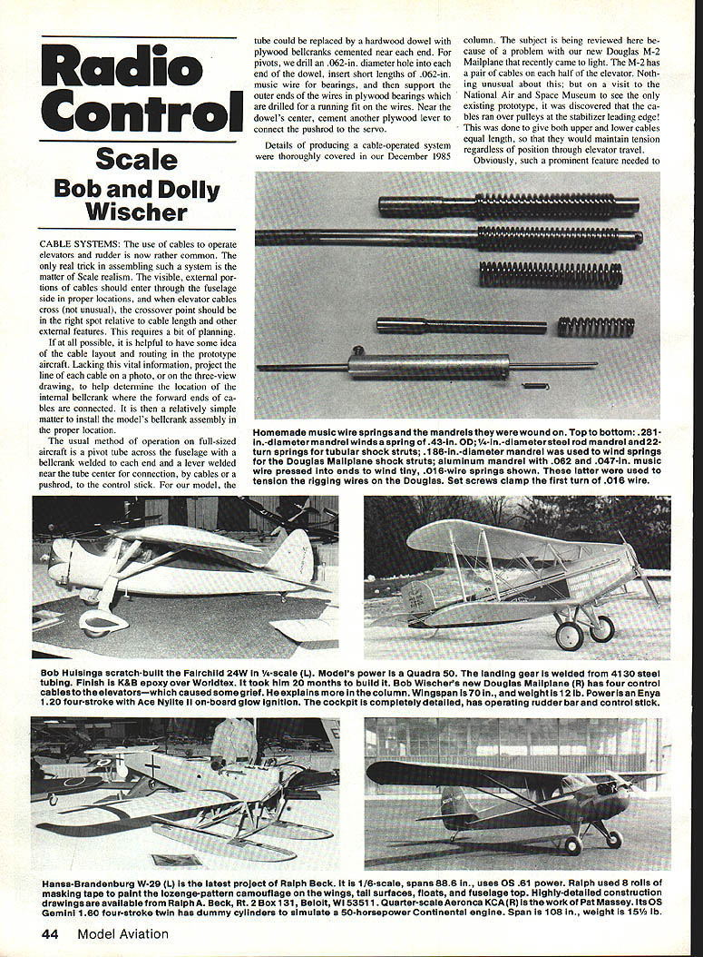
A reader asked for an explanation of the technique used to make springs for special applications. Off-the-shelf springs (compression and tension) are available from hardware stores, but when they don't fit the application it helps to know how to make your own. We have made compression springs for landing-gear struts and other uses at home.
Winding springs on a mandrel is simple. Anyone with access to a lathe can produce springs quickly. Slow the lathe spindle with belt pulleys and back gears to about one revolution per second (slower is better). If a lathe isn't available, mount the mandrel in a hardwood block clamped in a vise. Fasten a crank lever to one end with a setscrew to rotate the mandrel manually; lever length of about eight inches to one foot is satisfactory for winding springs from light music wire up to .062-in. diameter.
Procedure:
- Drill a cross hole through the mandrel to accept the chosen wire size and bend the music wire 90° for insertion in the cross hole.
- Winding requires two people: one operates the lathe or turns the handle, the other applies tension to the free end of the wire to force it tightly around the mandrel as the spring is wound.
- Grip the wire's free end with pliers or a vice-grip; ordinary pliers may slip under tension. If the grip slips, the free end can whip and entangle the operator — exercise care.
- During winding the spring shortens. When finished, anneal the spring in a propane flame until cherry red, then allow it to cool slowly. Compress the spring in a vise several times to relax internal stresses. Optionally, stress relieve at about 650°F.
Tension springs (with hooks at each end) normally have initial tension at the ends. For rigging wires, we sometimes remove one hook to solder the spring directly to the wire, leaving only one hook.
Compression springs for shock-absorbing landing gear use heavier wire (.047, .055, .062 in.) and have evenly spaced coil openings. To adjust length, wind a few close-wound turns at each end, then remove end coils with a Dremel cutoff disc if needed. Obtaining exact length on the first try is rare; expect scrap and save it for future use.
Technique tips:
- To make the spaced coils, hold the vise-grip at a right angle to the mandrel centerline for two or three revolutions, then swing the plier and wire slightly off to one side to create space between coils. Near the end, return to the 90° position to wind several close-wound turns.
- Professional shops sometimes insert a soft copper wire between coils after the first close-wound section to ensure consistent spacing; this requires a second hole in the mandrel to hold the soft wire.
Producing two identical springs by hand is difficult, but springs within about 10% of each other are usually usable. Add washers or spacers to increase length or cut off ends as needed.
Balance the variables — wire diameter and number of active turns — to achieve the desired spring rate. Use the following formula to estimate spring rate:
Load (spring rate) = (11,500,000 * d^4) / (8 * D^3 * N)
Where:
- d = wire diameter (inches)
- D = mean spring diameter = outside diameter − d (inches)
- N = number of active turns
- 11,500,000 = torsional modulus of elasticity for music wire (pounds/in^2)
- The formula gives pounds per inch of deflection starting from the spring's free length.
To find the load at any deflection, multiply the rate by the deflection in inches. Remember the spring may be partially loaded in a rebounding or preloaded installation.
Example: For an airplane weighing 12 lb. (6 lb. on each main gear leg), a compression spring made from .055-in. diameter wire, outside diameter .406 in., and 22 active turns can be installed in a .500-in. OD strut. Wound to a free length of about 2.62 in., the spring could deflect about 1.25 in. to absorb a landing load of roughly 17 lb. per leg — about three times the model's weight. Because wire tends to spring back after winding, the mandrel diameter is chosen smaller (for example, wound on a .25-in. mandrel to yield a .406-in. OD spring).
Be aware that too many turns of small wire will not support the weight; too few turns of large wire will reach solid length after a short deflection and take a set. Trial-and-error calculations and practical testing are part of the process.
Safety note: gripping the wire securely and keeping hands clear of the whipping end is essential. Use heavy pliers or a vice-grip and appropriate eye and hand protection.
Model notes / Examples
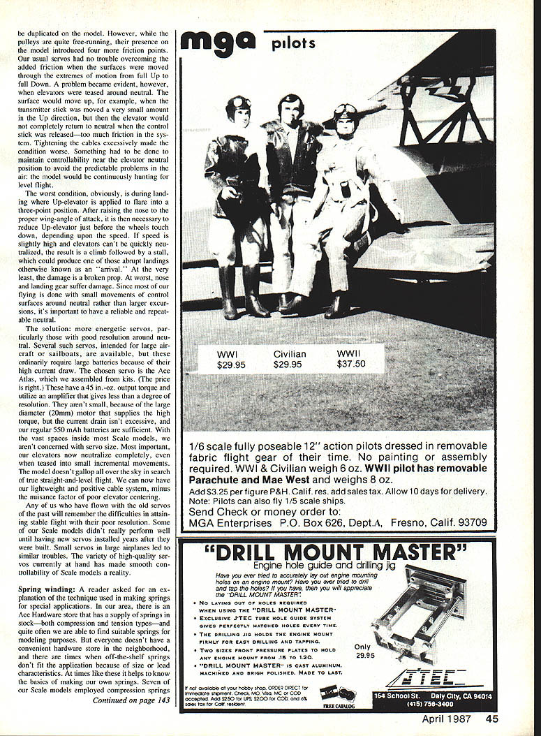
- Bob Huisinga's scratch-built Fairchild 24 (1/5-scale) uses Quadra 50 power. Landing gear is welded 4130 steel tubing; finish is K&B epoxy over Worldtex. It took him 20 months to build.
- Bob Wischer's Douglas Mailplane (1/3-scale): four control cables for the elevators caused the friction problems described above. Wingspan 187 in., weight 18.5 lb. Power: Enya 120 four-stroke with an Ace Nylite II onboard glow ignition. The cockpit is fully detailed with an operating rudder bar and control stick.
- Hansa-Brandenburg W-29 (1/4-scale) is Ralph Beck's latest project. His 1/8-scale work spans 88 in. and uses .061 power. Ralph used eight rolls of masking tape to paint the lozenge-pattern camouflage. Detailed construction drawings are available from Ralph Beck, Rt. 2, Box 131, Beloit, WI 53511.
- Quarter-scale Aeronca KCA-R work by Pat Massey uses an OS Gemini 180 four-stroke twin with dummy cylinders to simulate a 50-hp Continental engine. Span 108 in., weight 15.5 lb.
Bob and Dolly Wischer S-221 Lapham Peak Rd. Delafield, WI 53018
Transcribed from original scans by AI. Minor OCR errors may remain.

