
Radio Control: Scale
Bob and Dolly Wischer
Balsa Dowels and a Paris Hobby Shop
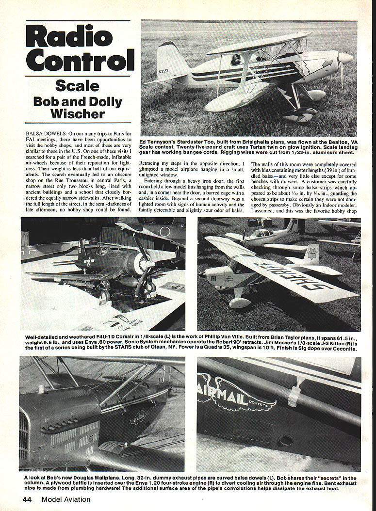
On our many trips to Paris for FAI meetings, there have been opportunities to visit the hobby shops, and most of these are very similar to those in the U.S. On one of these visits I searched for a pair of the French-made, inflatable air-wheels because of their reputation for lightness. Their weight is less than half of our equivalents.
The search eventually led to an obscure shop on the Rue Trousseau in central Paris, a narrow street only two blocks long, lined with ancient buildings and a school that closely bordered the equally narrow sidewalks. After walking the full length of the street, in the semi-darkness of late afternoon, no hobby shop could be found. Retracing my steps in the opposite direction, I glimpsed a model airplane hanging in a small unlighted window.
Entering through a heavy iron door, the first room held a few model kits hanging from the walls and, in a corner near the door, a barred cage with a cashier inside. Beyond a second doorway was a lighted room with signs of human activity and the faintly detectable and slightly sour odor of balsa.
The walls of this room were completely covered with bins containing meter lengths (39 in.) of bundled balsa — and very little else except for some benches with drawers. A customer was carefully checking through some balsa strips which appeared to be about 1/2 in. by 1/8 in., guarding the chosen strips to make certain they were not damaged by passersby. Obviously an indoor modeler, I assumed, and this was the favorite hobby shop of the indoor flyers.
Asking for wheels, in English, brought blank stares at the foreigner who dared invade. From the two persons who seemed to be workers, I succeeded in gaining attention by making my needs known with a pencil sketch of a wheel with metric diameter dimension. Aha! What I wanted was "roue," the French word for wheel. A drawer was opened, and to my surprise a pair of wheels appeared. The cashier showed the price — about half what I had paid in the U.S. — and I paid at the exit. It was then that I began to pay particular attention to the contents of the balsa bins.
Never have I seen such a large quantity of balsa except in the Sig warehouse. This place must have been the major balsa supplier for all of France. Examined more closely, some of the balsa sticks were not the familiar square and rectangular shapes but were round dowels of various diameters. I would have liked to ask their purpose, but the language barrier terminated conversation. "I'm going flying" — words that conjure up images of battles, balky engines, and carefree days at the field.
Making Large Balsa Dowels
On returning home and in my workshop, a new Douglas M-2 Mailplane needed a pair of curved exhaust pipes 3/8 in. diameter and 33 in. long. After checking the weight of aluminum tubing and finding a pair would weigh about six ounces, and after learning that local tubing suppliers wanted minimum orders of $50, it seemed prudent to choose an alternate material. I decided the pipes should be made of balsa, which reminded me of the Paris hobby shop and its supply of round balsa. I anticipated having to make some 1-1/4-in.-diameter, 33-in.-long balsa dowels.
Starting with square sticks slightly oversize at 1-3/8 in., a table saw set at 45° removed the corners to produce an octagonal shape of equal sides. The blade was then reset to 22 1/2° and the corners removed to produce 16-sided, nearly round sticks — the result needed for scratch-builders.
These needed only to be pushed through a 1-1/4-in.-diameter hole drilled in a steel plate to shape the dowel to a perfectly round form. For smaller diameters, a saw isn't required — just push square balsa through successively smaller holes in a steel plate. A few strokes with sandpaper wrapped around the dowel smooths the surface.
Curving and Hollowing
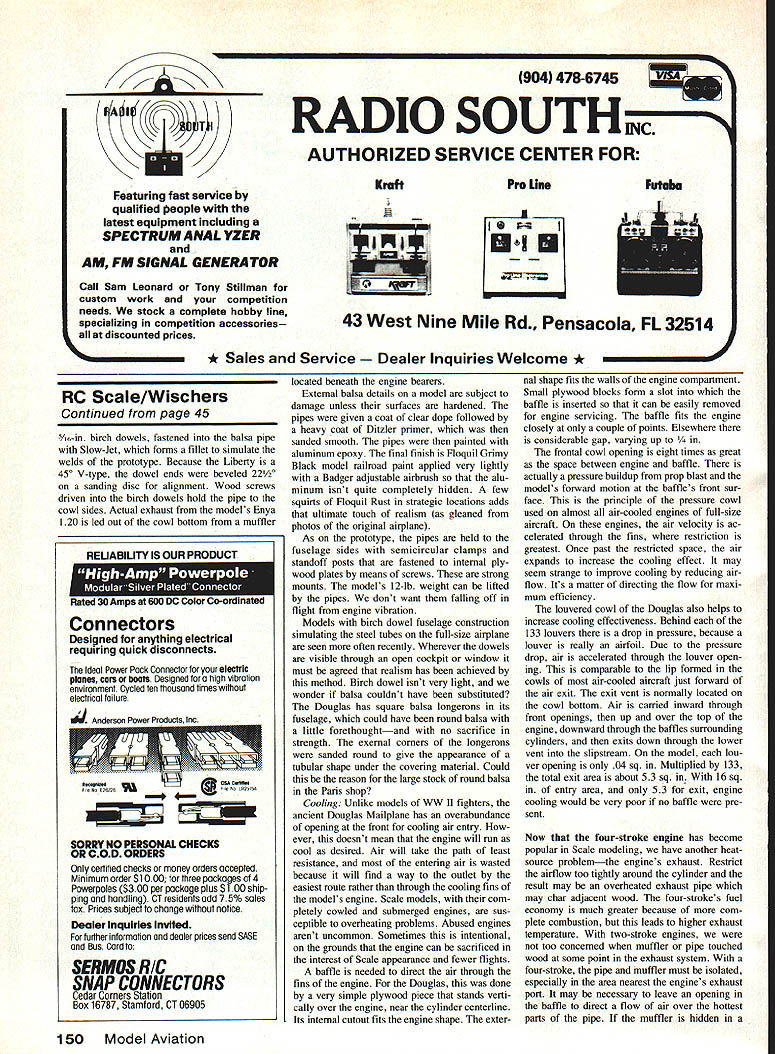
For the Douglas, the pipes were curved by soaking them in hot water for about one minute and then drying while being held in the curved shape by pinning to a plank. They were over-bent a bit to allow for some spring-back. The hollowing out of each pipe was simulated by grafting on a short piece of aluminum tube, bored out to a very thin wall. The forward ends are tapered, with six short stacks on each side extending to the 12 cylinders of the dummy Liberty engine. The stacks are located beneath the engine bearers.
Surface Hardening and Finish
External balsa details on a model are subject to damage unless their surfaces are hardened. The balsa pieces were given a coat of clear dope followed by a heavy coat of Ditzler primer, which was then sanded smooth. The pipes were then painted with aluminum epoxy. The final finish is Floquil Grimy Black model railroad paint applied very lightly with a Badger adjustable airbrush so that the aluminum isn't quite completely hidden. A few squirts of Floquil Rust in strategic locations adds that ultimate touch of realism (as gleaned from photos of the original airplane).
Mounting and Strength
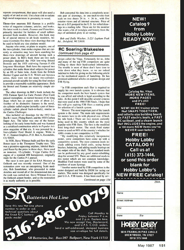
As on the prototype, the pipes are held to the fuselage sides with semicircular clamps and standoff posts that are fastened to internal plywood plates by means of screws. These are strong mounts — the model's 1/2-lb. weight can be lifted by the pipes. We don't want them falling off in flight from engine vibration.
Fuselage Dowels and Realism
Models with birch dowel fuselage construction simulating the steel tubes on the full-size airplane are seen more often recently. Wherever the dowels are visible through an open cockpit or window it must be agreed that realism has been achieved by this method. Birch dowel isn't very light, and we wonder if balsa couldn't have been substituted. The Douglas has square balsa longerons in its fuselage, which could have been round balsa with a little forethought — and with no sacrifice in strength. The external corners of the longerons were sanded round to give the appearance of a tubular spar under the covering material. Could this be the reason for the large stock of round balsa in the Paris shop?
Cooling
Unlike models of WWII fighters, the ancient Douglas Mailplane has an overabundance of opening at the front for cooling air entry. However, this doesn't mean that the engine will run as cool as desired. Air will take the path of least resistance, and most of the entering air is wasted because it will find a way to the outlet by the easiest route rather than through the cooling fins of the model's engine. Scale models, with their complex cowled and submerged engines, are susceptible to overheating problems. Abused engines aren't uncommon. Sometimes this is intentional, on the grounds that the engine can be sacrificed in the interest of scale appearance and fierce flights.
A baffle is needed to direct the air through the fins of the engine. For the Douglas, this was done by a very simple plywood piece that stands vertically over the engine, near the cylinder centerline. Its internal cutout fits the engine shape. The external shape fits the walls of the engine compartment. Small plywood blocks form a slot into which the baffle is inserted so that it can be easily removed for engine servicing. The baffle fits the engine closely at only a couple of points. Elsewhere there is considerable gap, varying up to 1/4 in.
The frontal cowl opening is eight times as great as the space between engine and baffle. There is actually a pressure build-up from prop blast and the model's forward motion at the baffle's front surface. This is the principle of the pressure cowl used on almost all air-cooled engines of full-size aircraft. On these engines, the air velocity is accelerated through the fins, where restriction is greatest. To make the restricted space, the air expands to increase the cooling effect. It may seem strange to improve cooling by reducing airflow. It's a matter of directing the flow for maximum efficiency.
The louvered cowl of the Douglas also helps to increase cooling effectiveness. Behind each of the 133 louver holes there is a drop in pressure, because a louver is really an airfoil. Due to the pressure drop, air is accelerated through the louver opening. This is comparable to the lip formed in the cowl of most air-cooled aircraft just forward of the air exit. The exit vent is normally located on the cowling bottom. Air is carried inward through front openings and then up and over the top of the engine, downward through the cylinders surrounding the fins, and then exits down through the lower vents into the slipstream. On the model, each louver opening is only 0.04 sq. in. Multiplied by 133, the total exit area is about 5.3 sq. in. With 16 sq. in. of entry area, and only 5.3 for exit, engine cooling would be very poor if no baffle were present.
Exhaust Heat and Heat Protection
Now that the four-stroke engine has become popular in scale modeling, we have another heat-source problem — the engine's exhaust. Restricting the airflow tightly around the cylinder may result in an overheated exhaust pipe which may char adjacent wood. The four-stroke's fuel economy is much greater because of more complete combustion, but this leads to higher exhaust temperature. With two-stroke engines, we were not too concerned when mufflers or pipe touched wood at some point in the exhaust system. With a four-stroke, the pipe and muffler must be isolated from the structure.
It may be necessary to leave an opening in the baffle to direct a flow of air over the hottest parts of the pipe. If the muffler is hidden in a cowling or tucked behind the firewall in a separate compartment, that space will also need a supply of air and an exit. Use a heat sink to radiate high metal temperature in proximity to wood. Be certain hidden mufflers are backed by heat-resistant material.
Three-View Sources
Bill Hannan — Peanuts and Pistachios
Bill Hannan is a prolific writer of magazine columns, articles, and books. His latest work is a book, Peanuts and Pistachios, primarily intended for builders of small rubber-powered scale models. However, this book may be of special interest to all scale modelers, because it contains five three-view drawings that can be used to build any size airplane model.
Anyone who owns, or plans to acquire, one of the two-cylinder, four-stroke engines that are currently so attractive may have been searching for three-view drawings of aircraft having such a power plant. In Bill's book there are two such prototypes depicted: the 1924 two-wing Bristol Brownie and the 1935 mid-wing Farman F.450 long-nose Moustique. Both have the exposed two cylinders that make them ideal subjects for power by an OS or Saito twin. Aside from the British Hawker Cygnet and the U.S. Welch and Aeronca series, there were not too many two-cylinder-powered aircraft suitable for using the four-strokes to provide a reasonably scale-like appearance. Both the Bristol and Farman are relatively simple aircraft.
The other drawings in Bill's book include:
- the 1926 Farman Sport La Carte Postale (Post Card) parasol monoplane, so named because of its wing shape which has an aspect ratio of about 2:1. Another of its distinctive features is the novel six-cylinder radial engine (actually a pair of three-cylinder radials placed back-to-back), similar to the Curtiss Challenger;
- the 1932 Gee Bee R-1 racer, Flying Barrel;
- the 1935 Corben Super Ace, one of the better-looking of the early home-builts, which was powered by a four-cylinder Ford Model A engine and was featured as a serialized construction article in Popular Aviation magazine of the era.
Write to W. C. Hannan Graphics, P.O. Box A, Escondido, CA 92025.
Steve Wittman — Bonzo Racer Drawings
In 1938, Steve Wittman built and flew the early Bonzo racer in the Thompson Trophy race. This was a primitive-looking airplane, labeled "Back-yard Racer" by the press in those days. Steve used an immense, 12-cylinder, Y-type Curtiss D-12 engine of a nominal 400 horsepower, originally made for the Curtiss P-1 pursuit.
The racer is now part of the EAA Museum at Oshkosh and was recently restored. One of the restoration crew was an enterprising scale modeler, Bob Sonnleitner, who proceeded to make sketches and record all of the dimensional data as the work was carried out. Steve Wittman lives on the Oshkosh airport border, and so the restoration is as nearly authentic as possible.
Bob converted his data into a completely accurate pair of drawings, in one-inch-to-one-foot scale on two sheets 24 in. x 36 in., with five exterior views and all internal structure. Price of the set is $13 postpaid in the U.S. for rolled drawings in a mailing tube. These are for the modeler who wants a bit of nostalgia and history from the days of unlimited glory in air racing.
Bob and Dolly Wischer 3-221 Lapham Peak Rd., Delafield, WI 53115
Transcribed from original scans by AI. Minor OCR errors may remain.

