
Radio Control: Scale
By Bob and Dolly Wischer
Operational Details
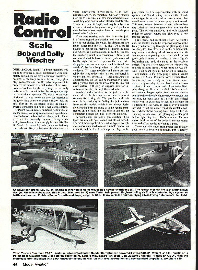
Scale modelers who aspire to produce a true scale masterpiece face a common problem when using a completely cowled engine: how to hide the glow-plug connector and provide for needle-valve adjustment while preserving a smooth external cowl surface. Some minimize the appearance of these necessities; others tolerate a small hole in the cowl for plug insertion or use the smallest external connector they can find.
Glow-plug Connector
- Our own scale aircraft (about 20) all use an open-frame, two-conductor sub-miniature phone jack chosen for easy availability and longevity (industry standard).
- These jacks come in two sizes: 1/8-in. sub-miniature and 1/4-in. miniature. The 1/8-in. size is smaller and less conspicuous but somewhat fragile and susceptible to vibration fatigue, an increasing concern with the popularity of four-stroke engines. The 1/4-in. jack is more rugged but bulkier.
Jack Location and Mounting
- If no convenient hiding place exists, the smaller 1/8-in. jack is often mounted on the cowl side where it is less conspicuous.
- On larger models the tiny nut and barrel may be visible but not obtrusive. If appearance is objectionable, mount the jack on a separate plywood plate recessed from the internal cowl surface so only a small hole is exposed.
- An alternate hidden location is under the fuselage at a vent opening, but this can make the jack hard to find and access (inverting the model is often necessary). Completely hidden jacks have caused preflight vexations and are less popular for that reason.
Jack Types and On-board Ignition
- Two jack configurations are offered: open-circuit and closed-circuit. For most model applications either type is acceptable since the connection is made to the tip and ferrule of the phone plug.
- Closed-circuit jacks were useful in early on-board ignition experiments because an extra contact would open when the phone plug was inserted, disconnecting the on-board battery (useful as nose weight). That system used a throttle-actuated switch to connect battery and glow plug at low throttle.
- The flaw: at flight end the throttle must be reopened to prevent battery discharge through the glow plug. This was often forgotten, leaving the on-board battery dead.
- Current practice: use a separate switch. Glow ignition is switched on at the beginning and off at the end of flights. Using the same receiver switch with two actuators side-by-side reduces forgetfulness. Some on-board systems (e.g., Ace Ni-Lite III) include the switch.
Glow-plug Connectors and Remote Heads
- The Model Products Corp. Remote Headlock tiny connector requires an extra ~1/8 in. clearance above the glow-plug tip and provides quick connect-release for easy plug changes.
- If clearance isn’t available, a reliable homemade connector is a 3/16-in. brass wheel collar with an extra hole drilled in the edge for soldering the lead. To avoid accidental contact with cylinder-head fins, use a fiber insulating washer over the glow-plug center post before tightening the collar set screw.
- Disadvantage of the collar: additional time and effort when changing plugs.
Wiring Recommendations
- Keep connector wire length from the phone jack to the glow plug to a minimum for flexibility.
- For vibration conditions, multi-stranded wire is best. For current-carrying capacity we prefer 16 or 18 gauge. (Jumper 16-gauge wire may have many strands for extreme flexibility.)
- Note: stranded wire is susceptible to breakage near solder joints because solder wicks along the strands. Fracture often occurs where the solder terminates. Supporting the wire near the solder joint reduces this problem.
Making an Adapter Cord (to match a glow connector to a phone plug)
If you use the same battery across multiple airplanes, an adapter cord that converts a glow-plug connector to a phone plug is handy and easy to make:
- Find an old burned-out glow plug (Fox plugs work well).
- Place it in a vise, threaded end upward, and file off enough steel to expose the inner core (usually brass or other nonferrous material).
- Solder a 1/4-in. length of 7/64-in. O.D. brass tube over the exposed inner core.
- Solder a suitable length of stranded wire into the exposed tube end.
- File a flat on the remaining threads of the plug and solder a second wire to that flat.
- Solder a phone plug to the other ends of the wires.
- Protect solder joints with short lengths of heat-shrink tubing and wrap with electrical tape.
- Make several adapters; they tend to get lost.
- Warning: the exposed phone tip can be a fire hazard in a field box if left connected to the battery and resting against anything metallic. Opposite polarities can be separated by only ~1/32 in.
Needle Valve Extension
- Past methods to adjust carburetor needle valves on fully enclosed engines used flexible cables or bevel gears to change motion 90°. These worked but were complex and finicky.
- A simple and effective solution: make a needle-valve extension using hexagonal shaft/tube coupled to a matching hex-socket nut driver (hobby-shop nut drivers).
- Materials and method:
- Use K&S 1/16-in. hexagon brass tube (other sizes can be used; 5/32- or 3/16-in. through-cowl bore may be required).
- The tube must be exactly aligned with the engine needle-valve centerline.
- If the needle has an axial hole and a cross hole for a setscrew, file a small flat on the hex tube to form a stop for the setscrew and tighten to secure.
- To prevent the setscrew from crushing the thin tube, solder a short length of .062-in. diameter music wire into the tube end.
- Cut tube length so it reaches the cowl outer surface when the needle is set at optimum position.
- Solder another short length of music wire into the outer end of the hex tube, letting it extend about 1/8 in.
- In operation, place the open end of the hex driver over the music-wire tip and rotate until it engages the hex tube. This provides positive drive, resists vibration, and requires no machining.
- The 1/8-in. and 3/32-in. hex socket drivers will fit corresponding K&S tubing sizes, but may require larger through-cowl holes and more complex attachment to some needles.
Maxey Hester once said, “Never build a Scale model without provision for carburetor adjustment.” We agree. This needle-extension system is simple, positive, and especially suited to four-stroke engines where the needle is safely behind the propeller.
Transcribed from original scans by AI. Minor OCR errors may remain.

