
Radio Control: Scale
By Bob and Dolly Wischer
Scale Math
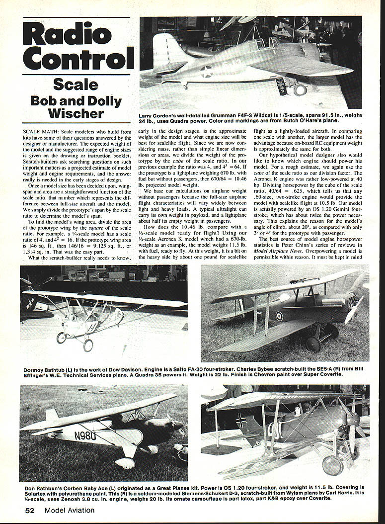
Scale modelers who build from kits have some of the questions answered by the designer or manufacturer. The expected weight of the model and the suggested range of engine sizes are given on the drawing or in the instruction booklet. Scratch-builders must ask searching questions on such important matters as projected model weight and engine requirements, and the answers are really needed in the early stages of design.
Once a model size has been decided upon, wingspan and area are a straightforward function of the scale ratio — the number which represents the difference between the full‑size aircraft and the model. We simply divide the prototype's span by the scale ratio to determine the model's span.
To find the model's wing area, divide the area of the prototype wing by the square of the scale ratio. For example, a 1/4‑scale model has a scale ratio of 4, and 4 squared = 16. If the prototype wing area is 146 sq. ft., then 146 / 16 = 9.125 sq. ft., or 1,314 sq. in.
What the scratch-builder really needs to know early in the design stages is the approximate weight of the model and what engine size will be best for scale-like flight. Since we are now considering mass rather than simple linear dimensions or areas, we divide the weight of the prototype by the cube of the scale ratio.
Example:
- Scale ratio = 4 (1/4 scale) → 4 cubed = 64.
- Prototype weight (lightplane, with fuel but without passengers) = 670 lb.
- Projected model weight = 670 / 64 = 10.46 lb.
We base our calculations on airplane weight without passengers because full-size airplane flight characteristics vary widely between light and heavy loads. A typical ultralight can carry its own weight in payload, and a lightplane about half its empty weight in passengers.
How does 10.46 lb. compare with a 1/4‑scale model ready for flight? Using our 1/4‑scale Aeronca K (prototype weight 670 lb.) as an example, the model weighs 11.5 lb. with fuel, ready to fly. At this weight it is a bit heavy — about one pound over our projection — for scale-like flight. In comparing one scale with another, the larger model usually has the advantage because on-board RC equipment weight is approximately the same for both.
For a rough estimate of engine size we again use the cube of the scale ratio as the division factor. The Aeronca K engine was rather low-powered at 40 hp. Dividing horsepower by the cube of the scale ratio: 40 / 64 = 0.625, which tells us that any .60‑size, two-stroke engine would provide the model with scale-like flight at about 10.5 lb. Our model is actually powered by an OS .120 Gemini four‑stroke, which has about twice the power necessary. This explains the model’s angle of climb (about 20°) as compared with only 3° or 4° for the prototype with passengers.
The best source of model engine horsepower statistics is Peter Chinn's series of reviews in Model Airplane News. Overpowering a model is permissible within reason; it must be kept in mind that too heavy an engine could increase wing loading on a small model. Underpowered models usually go back to the workshop in a basket.
Wing Loading
Now that we know the model's wing area and its approximate weight, it is a simple matter to extrapolate projected wing loading. Since wing loading of model airplanes is ordinarily expressed in ounces per square foot, first convert the projected weight to ounces, then divide by area in square feet.
With our Aeronca example:
- Weight = 11.5 lb. → 11.5 × 16 = 184 oz. (Note: the article's earlier projection used 10.46 lb. = 167.36 oz; the example uses the actual ready-to-fly weight.)
- Area = 9.125 sq. ft.
- Wing loading = 184 oz. / 9.125 sq. ft. = 20.2 oz. per sq. ft.
(Using the projection of 10.46 lb.: 10.46 × 16 = 167.36 oz.; 167.36 / 9.125 = 18.4 oz. per sq. ft.)
In reality, because the Aeronca model came out slightly heavier than expected and we added a weighty dummy pilot, its wing loading is 22 oz. per sq. ft., with fuel.
This calculation is of particular value for determining whether the model will be manageable in flight. Experience says that 30 oz. per sq. ft. is about the upper limit for smaller models with .60‑size engines, while Giant Scale airplanes can go as high as 45 oz. The variation is the result of change in Reynolds numbers due to size, but this series of calculations is meant to be kept simple.
Of course, simplified calculations can go seriously awry when applied to some aircraft, such as overpowered, heavy types intended for carrying great loads, or to aircraft with behavior contrary to scale modeling principles. Our model's weight varies little from flight beginning to end, and so, to be useful, the calculations must be tempered with reason. Fuel loads on our models don't approach those of full‑size aircraft, which may be half of gross weight for world‑circling airliners. Calculations of power requirements based on takeoff horsepower can also lead us astray, since high‑powered aircraft use full output only for short durations.
Examples
Douglas A‑20G attack bomber:
- Full‑size empty weight = 17,000 lb.
- Scale ratio = 19.6 → model span = 76.6 in.
- Calculated model weight = 17,000 / (19.6^3) ≈ 19 lb.
- Actual model weight = 14 lb. (due to all‑out weight reduction in construction)
- Wing loading at 14 lb. = about 44 oz. per sq. ft.
- Handling was a bit precarious, with climb and glide speeds about equal.
- From the 1,275‑hp Wright radials, power for the model calculates to ≈ 1.4 hp; the model's .40 engines peak at about 1.2 hp, which is acceptable for a 14‑lb. weight.
Douglas Mailplane:
- Scale ratio = 6.857 → span = 69.4 in.
- Calculations from the full‑size included a half‑ton of fuel, which would have brought projected model weight up to 15.4 lb.
- Actual model weight = 12 lb.; wing loading = 22 oz. per sq. ft. The model will never be expected to lift half its weight in fuel.
- Power requirements, calculated from the 400‑hp Liberty engine of the prototype divided by 6.857^3 (≈ 322.4), is about 1.2 hp, adequately supplied by its Enya .120 four‑stroke.
- Because the model doesn't carry the equivalent of a ton in fuel and mail load, calculations cannot realistically begin with published gross‑weight figures.
Ryan SCW:
- Scale ratio = 5.65 → model weight should be about 10.25 lb., which is almost exactly correct.
- Horsepower requirement ≈ 0.8 hp; any standard .60 engine would suffice.
- The Super Tiger .60 in the model is rated at well over one horsepower, allowing use of a larger‑diameter prop for greater efficiency around the radial engine cowl.
- Calculated wing loading ≈ 23.6 oz. per sq. ft.; actual = 25.9 oz. per sq. ft.
- The model performed as predicted; estimated values are useful but quickly discarded when they fall outside expectations.
Construction and Weight Control
Control of weight during design and construction is one of the more difficult tasks for the scratch‑builder. Having made some calculations to determine an estimated wing loading, the builder faces the serious problem of selecting materials and placing strengthening structural members to avoid exceeding the desired maximum weight. When a choice must be made, our strict policy is to choose the lighter material, on the grounds that a crashed model will have some parts badly damaged and a heavy structure only compounds the damage.
Wide variations in strength should be avoided. For example, a strong fuselage can survive a bad landing due to a stall while a weak wing structure is shattered. If the stall occurred as a result of an overweight condition, the heavy fuselage may well have been a contributing factor. We can't build protection against pilot error.
As for a preferred construction method for weight reduction or ease of building in scale modeling, we must conclude that we don't have one. In fact, no two of our models have been built alike, even when duplicating an older model. For wings with open structure, the common framework of leading edge, trailing edge, ribs, and spars has many variations.
The new Douglas Mailplane has solid‑balsa‑plank leading edges that are partially sheared on the circular saw to minimize carving and sanding afterward.
- Advantage: No spars near the leading edge, only one spar near the trailing edge, and good airfoil shape retention.
- Disadvantage: This style of construction is expensive and could contribute to heavy weight unless special care is taken in selecting light balsa for the solid leading edges.
For wings that are completely sheet‑covered, we have tried foam as well as conventional rib construction and found no appreciable difference in final weight, strength, or building time. The electronic calculator has taken the sweat out of plotting airfoils, even for tapered wings with a dozen or more rib positions. Starting with N.S. Rice's Handbook of Airfoil Sections for Light Aircraft, an airfoil can be plotted and drawn to any size in minutes. The repetition in a tapered wing with many rib positions may be monotonous, but it is no worse than cutting them later from balsa sheet.
Some older scale models with non‑scale airfoils seem to fly just as well as later ones with true scale shapes. Maintaining a true airfoil shape on fabric‑covered wings is only partially successful, due to fabric sag between ribs on both models and full‑scale planes. One good reason to use the scale airfoil is appearance, but this depends upon the critical eye of the viewer. The use of scale airfoil shapes probably has greater effect on flight of larger models. A flat‑bottomed airfoil may be acceptable for Schoolyard Scale, but we would hesitate to use one on a small pylon racer.
Building a fuselage to meet low weight projections becomes less difficult as model size increases. It's the small model that suffers most from too‑high wing loading. Building in excess strength in a fuselage is a temptation to be resisted. After a bad landing, the strong fuselage merely produces larger pieces to be repaired.
Design Recommendations
To summarize, the scratch‑designer can make fairly accurate estimates of design parameters. If in doubt concerning engine size, choose the larger displacement to take advantage of using larger‑diameter propellers. Benefits include:
- Lower engine RPM for the same thrust (less noise).
- More efficient propellers because tips work outside the fuselage and wing downwash.
- Potentially reduced fuel consumption.
We have had no problems with overheating from large, slow‑turning props; the engines seem to wear forever. Excessive engine wear can be traced to overheating due to lean needle settings or inadequate ventilation, and these conditions can exist regardless of prop size. While the larger prop may not be of scale diameter, appearance is definitely improved.
The scratch‑builder has more positive control over center‑of‑gravity location. Using light balsa in the aft fuselage and tail surfaces can help move the all‑important balance point to a comfortable 25% position of the wing chord for first flights. Having an early estimate of total weight and observing nose and tail moments can be a definite aid in material selection.
Bob and Dolly Wischer S‑221 Lapham Peak Rd. Delafield, WI 53018
RC Scale/Wischers
Continued from page 53
Control of weight and accurate estimation of performance parameters are recurring themes in scale scratch‑building. Estimated values give the builder a starting point; the builder must then balance appearance, strength, and performance through careful material choice and construction technique.
Transcribed from original scans by AI. Minor OCR errors may remain.

