
Radio Control: Scale
Bob and Dolly Wischer
Piano hinge
The ubiquitous piano hinge is used on many aircraft for cowl and hatch hinge joints. It is used for good reason: it affords a very secure hinge arrangement with light weight and adaptability. Its only real drawback is its inability to follow a curved line. If we see a piano hinge, be assured that there are no compound curves in the cowl.
A piano hinge is the continuation of interleaving hinge points with a long wire passing through all segments. It can be of any length.
We have seen models with operational piano hinges, and some of these were quite well made, considering the fact that the modeler had produced them by hand. With small models, however, the scale appearance is often lost due to difficulty in obtaining true dimensions in diameter—especially in the spacing between hinge segments. Our best efforts have been in the direction of a reasonable simulation. We are always flattered when someone asks their source on the assumption that they are a commercial item for purchase.
For models in the scale range of 1/6 to 1/8, we use the easily obtainable 1/16-in. aluminum tube from the hobby shop and add grooves at regular spacing to simulate the joints in a piano hinge. The grooves can be made by rolling the tube beneath a single-edge razor blade, but this requires a very deft touch and extreme care to avoid cutting directly through the tube.
The best system we have found for impressing the grooves is on our lathe. The tube is gripped in a three-jaw chuck and an X-Acto razor saw is held gently against the tube as close as possible to the jaws. The lathe must be stopped and started for each groove as the tube is moved progressively outward.
Lacking a lathe, there is another method. A V-groove is cut into the length of a hardwood block. We produce the V-groove by setting our circular saw blade at a 45° angle, with the blade extending only about .045 to .050 in. above the table top. When the aluminum tube is laid in this groove, it can't escape while it is twirled under a single-edge razor blade or an X-Acto razor saw. Again, a light touch is needed to avoid making small pieces.
We now have a length of aluminum tube that has become quite fragile and flexible. If it is to be applied to the model by setting into the hollow formed between adjacent cowl plates, it can be used directly by gluing into place with a flexible cement such as Wilhold R/C 56.
If the tube is to be fastened to the outer surface of a cowl where no hollow exists, the illusion of a piano hinge is lost because the tube stands too high. To remedy this, return the tube to the hardwood V-block and file away one side to obtain a flat surface for gluing. For best appearance, remove aluminum so that the file comes close to breaking through the tube's inside diameter. Only a tiny amount of R/C 56 is used to fasten the tube in place. Remove excess glue with a sharp toothpick or knife blade. The glue dries clear and somewhat rubbery.
We use R/C 56 to fasten all of the aluminum metalwork to the balsa or plywood substructure of our models, with never a joint failure. In fact, the metal is bent to a useless shape if one tries to remove it afterward.
Cowl latch
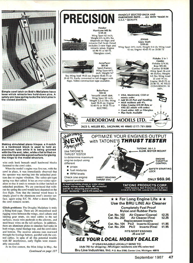
In the photo showing the piano hinge on the cowl of our Douglas Mailplane, note the two protrusions at the top. The larger one simulates the carburetor air intake for the prototype's Liberty V-12 engine. The smaller is a bent tube, with its opening facing forward, simulating a vent for the Liberty's oil tank. On our model, it was decided that this tube could be used as the operator for the cowl hold-down latch.
The operator is actually a short length of 3/32-in. music wire bent sharply 90°, its square-cut end painted flat black to simulate an open-ended tube. Rotating the operator 90° turns a brass plate soldered to its inner end, which pulls two 1/16-in. music wire latches inward to release the cowl.
When the model's engine was first run with the cowl in place, it was immediately observed that the operator was moving into the unlatched position due to engine vibration. A safety-pin-type spring was then added. It has an over-center operation so that it tends to remain in either latched or unlatched positions. We are convinced that without the spring the cowl would have departed on the first flight.
Making simulated piano hinges
A V-notch in a hardwood block is used to hold an aluminum tube while it is being grooved with the file and, later, while a flat is filed on one side to provide a good surface for gluing the hinge to the model structure.
Wire ends hook beneath small hardwood blocks fastened to the cowl sides.
Glitch problems
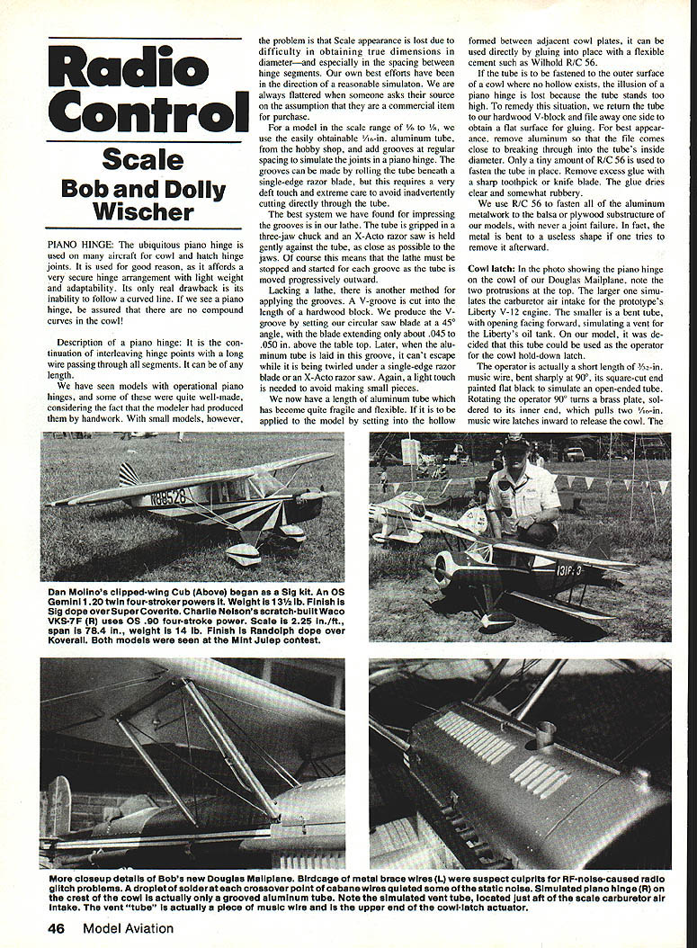
The Douglas Mailplane is truly a flying birdcage. There are 28 streamlined rigging wires between the wings, steel cabane and landing gear struts, six steel cables to the tail surfaces, music-wire pushrods to the ailerons, and steel brace wires to the tail surfaces. In addition, there are aluminum plates to simulate fuel tanks in both wings, a metal fuselage top, and the cowl sides and bottom. The receiver antenna runs rearward through the fuselage bottom, parallel with the cowl cables. In spite of this potential for RF interference, early flights were reasonably successful.
At its first contest, the Mint Julep in May, the model encountered a series of elevator and aileron glitches that threatened destruction. It was then that we remembered our first Douglas, built 17 years previously, and similar problems. One solution was to solder the points where the pairs of cabane wires crossed.
How about all of those other wires? In every case these wires terminated in wood and did not touch adjacent wires. Even the bellcranks for the control cables were made from plywood. Only the cabane brace wire ends were fastened into metal where they meet the 5/8-in. music wire struts. Vibrating metal is a prime source of RF interference, and single-cylinder four-stroke engines do vibrate.
All of the early flights were made without a dummy pilot in the cockpit. For a contest, the pilot's presence is a necessity because of the drastic loss in realism points during flight if the dummy isn't present. How could the plastic dummy pilot cause electrical noise in that one near-disastrous flight? A close examination revealed a likely reason. The Williams Bros.' plastic pilot figure was mounted on a strip of springy aluminum so that it could be snapped into place for flights and quickly removed for static judging. The ends of the aluminum strip pressed against the interior of the aluminum cockpit cowl, where engine vibration could rub metal against metal with only light pressure. We concluded this was asking for trouble. Insulating tubing is now glued to the mounting strip ends to electrically isolate it from contact with the cowl.
Only Scale modelers, with their unorthodox building methods and materials, are so susceptible to built-in problems. This brings to mind a sign we saw at the EAA Oshkosh convention, at the departure point for full-size aircraft. It succinctly warns: "DON'T DO NOTHING DUMB." Bad grammar, but effective. Our problem would have been solved had the dummy pilot been replaced.
Servo size
A reader asked for information on selecting servo sizes for Scale models. This is a question with many facets because of the wide variation in airplane type. The reader's basic concern was about the size of the label attached to his model indicating that it is quarter-scale, which to him meant large size and probable need for heavy-duty servos. The term "quarter-scale" is misleading. A small prototype aircraft, in 1/4-scale, could be a small model, and the servos needed for flight controls can be a standard type with output torque in the 30 to 40 in.-oz. range. It would normally be expected that such a model would weigh less than 15 lb.
Weight and speed of a Scale model are factors that determine necessary servo output torque. Scale ratio has little effect on servo size. A very active aerobatic-type model with large control surfaces moving from stop to stop will need servos with greater output. We have flown a 14-lb. model using Ace Bantam Midget servos having only 18 in.-oz. of torque. The model was definitely non-aerobatic, and no great demands were placed on the servos. For an aerobatic type, in the weight range up to 15 lb., servos with an output torque of 35 to 45 in.-oz. should do the job. For heavyweight models above 20 lb., use either the largest servos or two regular ones in parallel.
Ailerons and elevators on large models, up to 15 lb., are the control surfaces with greatest area and are most likely to overburden a weak servo. We have noticed a definite tendency for elevators to be unable to deflect fully during a dive after maneuvers such as recovery from a spin or a split-S. Because of the large size of elevators, the amount of deflection is actually visible from the ground, and we can see reduced motion during the pull-out after these maneuvers. The reduction is even more noticeable when the throttle is open and prop slipstream is adding to the elevator's burden. In other words, more altitude is needed to safely pull out of a dive with the throttle open. Our 38 in.-oz. servo would probably be considered marginal on this elevator. However, if that same airplane were never flown aerobatically, such a servo size would be adequate.
Basic differences in outputs of various servos can be traced to motor size. Practically all of our modern servos use a motor with 16 mm diameter, and this dimension is the determining factor in servo external dimensions. These servos have an output in the 40 in.-oz. range. For larger models or those intended for fast flight and violent maneuvers, servos such as the Ace Atlas are preferred. The Atlas is conservatively rated at 45 in.-oz. and uses a 20 mm diameter motor, which indicates larger case size and the need for 600 mAh batteries.
To avoid long pushrods to ailerons, some modelers use two servos, one to each aileron. The use of two servos in parallel for elevators also has merit. Of course, battery drain is increased, and 600 or 800 mAh batteries should be used, particularly when flights are long or there are many flights between charges. Heavy flight loads on a single servo also place an extra drain on batteries.
Hobbypoxy colors
Pettit Paint Co., manufacturers of Hobbypoxy products, has published formulas for mixing colors used on contemporary Israeli Air Force aircraft. The colors are Pale Green (FS-34227), Tan (FS-30219), Sand (FS-33531), and Light Gray (FS-36622). Two of these colors, Tan and Light Gray, are the same as those used on contemporary USAF aircraft and were published in this column earlier.
The formulas:
- Light Gray: 12 parts H10 White, 5 parts H55 Cream, 2 parts H70 Gray.
- Tan: 5 parts H65 Bright Red, 3 parts H10 White, 2 parts H49 Cub Yellow, 1 part H70 Gray, 1 part H81 Black.
- Pale Green: 11 parts H70 Gray, 7 parts H47 Bright Yellow, 1 part H24 Dark Blue, 1 part H10 White, 1 part H57 Bright Orange.
- Sand: 14 parts H55 Cream, 2 parts H70 Gray, 1 part H65 Bright Red, 1 part H10 White.
Bob and Dolly Wischer S-221 Lapham Peak Rd., Delafield, WI 53018.
Transcribed from original scans by AI. Minor OCR errors may remain.

