
Radio Control: Scale
Bob and Dolly Wischer
K-W Rally
On the weekend following Labor Day, the Kitchener–Waterloo Scale Rally was the gathering place for scale modelers from eastern Canada and the U.S. The usual number — 155 scale models — appeared despite expected rainy weather. Flights were held up for about two hours on Saturday afternoon but resumed immediately after the showers ceased.
The parking lot and campground adjacent to the flying field were already near full on Friday evening; by Saturday they were jammed with motor homes, tents, and vans. Groups congregated each evening after flights to converse and share experiences. The STARS Club of Olean, N.Y., invited attendees to a steak dinner. The Flying Dutchmen provided evening entertainment with a large-screen movie ("Top Gun") and a corn roast.
Radio control and impound system
The Flying Dutchmen Club again used their system for avoiding radio interference: six steel posts were driven into the ground, each with a list of frequencies attached and a detachable colored triangle on top. When a modeler was ready to fly, he parked his airplane at the post bearing his frequency and traded the triangle for his transmitter at the impound. The system worked 100% — there were no problems even though all six lines were in operation. Club-member monitors made certain there was good separation between transmitters at the flight line. Also, 31‑MHz adjacent-channel interference was nonexistent.
Night flight
Several hours after sunset, in total darkness, the sound of a running engine drew everyone back to the flying field. Steve Gray demonstrated night flight complete with low-level aerobatics, flying a lighted nine-foot-span model that appeared a combination of Cub and Telemaster. Steve used three flashlight heads for illumination in a novel arrangement:
- two mounted inside the cabin windows, projecting beams along the lower surfaces of the wings, and
- a third bulb and reflector aimed rearward through the fuselage interior, radiating through the model's plastic covering.
With this combination of lighting and a 4.8‑volt flight-pack battery wired through a servo for on‑off control, Steve was capable of flights equal to those in daylight. In total darkness the model was very bright.
Four-stroke engines and aerobatics
Although Canada has traditionally favored certain two-stroke engines, the four-stroke invasion has clearly taken hold. Two very impressive aircraft were a 1/4‑scale CAP 10 and a Laser model, both powered by Saito 2.70 twin‑cylinder engines. The Laser used ignition and an ultraslow idle with complete reliability. Both models were very aerobatic, especially in vertical maneuvers.
Jack Swift's clipped‑wing Monocoupe 110 in 1/3‑scale used a British Laser 90 four‑stroke engine. At only 12.5 lb, the airplane was highly aerobatic and capable of precision maneuvers. Paul Weigand's new clipped‑wing Taylorcraft (2.25‑scale, about 12 lb) with an OS 1.20 four‑stroke permitted truly unlimited aerobatics. All of these aerobatic models were flown with skill and precision throughout their routines.
Notable models and displays
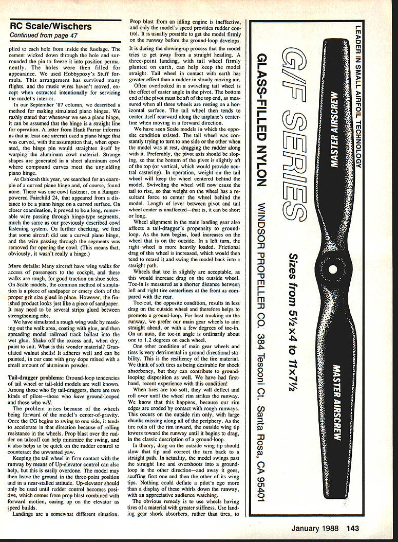
The STARS Club from Olean, N.Y., was the star of the show on both days. Six 1/4‑scale Bristol Scout biplanes flew loose formation — probably the last time such a quantity will be seen, as these models are getting old.
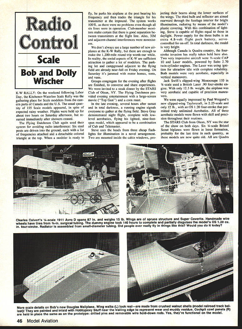
Charles Calvert's 1/6‑scale 1911 Avro D spans 87 in. and weighs 15 lb. Its wings are spruce structure covered with Super Coverite. Handmade wire wheels have tires made from surgical tubing. The dummy engine took 140 hours to complete and partially disguises the model's OS .120 cu‑in. four‑stroke. The radiator was assembled from small‑diameter tubing. Did people ever really fly things like this?
Bob Wischer’s 3/5‑scale Waco was powered by an engine nearly identical in appearance to the full‑size version. Pilots found it difficult to shift gaze from one model to another for more than a few seconds, at the risk of losing visual identification.
STARS member Bob Dunn displayed a new 1/4‑scale Curtiss A‑1 Triad floatplane — the first U.S. Naval aircraft of 1911. The model was flown on numerous occasions, using attached wheels at times. It flies very well despite extremely thin wings and a near‑scale airfoil section. Bob reported that the main float has insufficient displacement to support the model on the water and wondered whether the prototype experienced similar difficulties.
Ordinarily there are no prizes for judging at K‑W. This year an award was given for pilot’s choice: a genuine handcrafted dolly teddy.
Scale details and construction notes
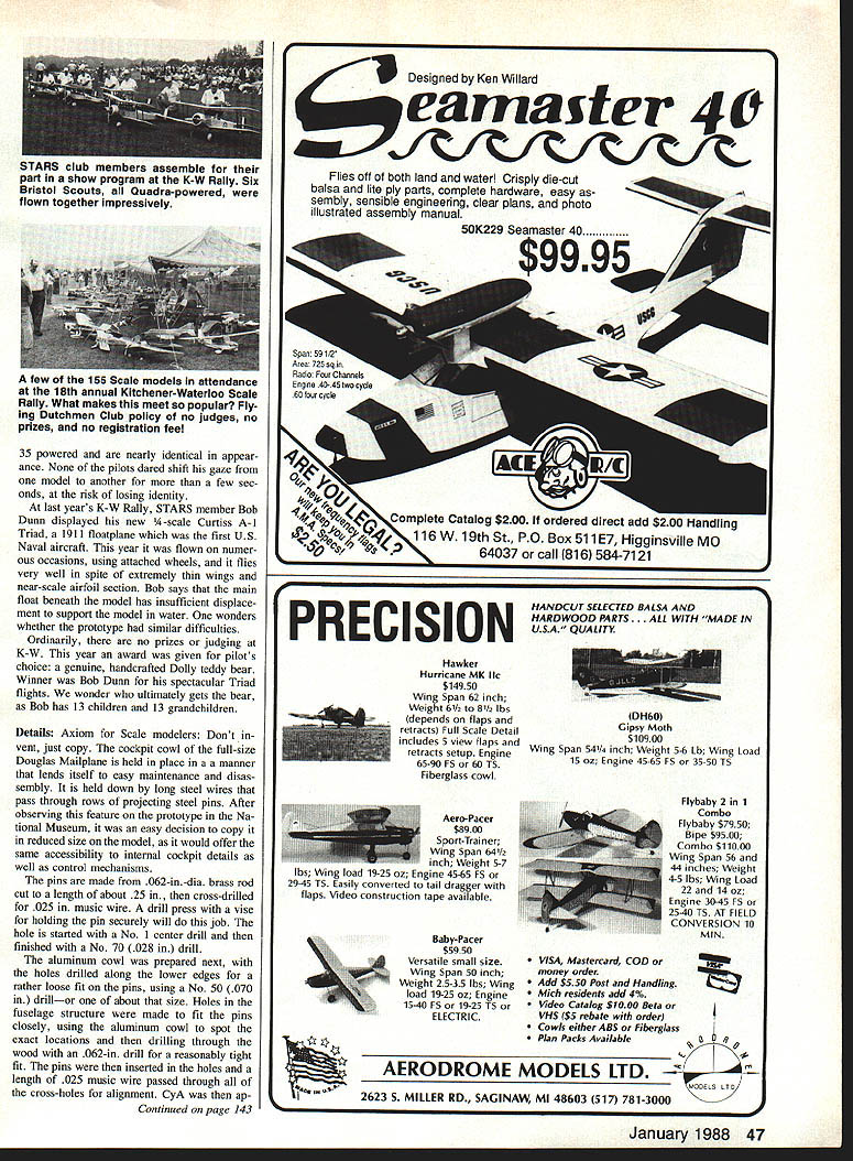
Cockpit and cowl panels are often held in place on scale models as on the prototype, by drilled pins and removable wire hold‑down rods. The pins may be secured by applying cement to each hole from inside the fuselage; the cement wicks down around the pin and freezes it into position. The holes are then filled for appearance. We used Hobbypoxy's Stuff for mending. This arrangement has survived many flights, and the music wires haven't moved except when intentionally extracted for servicing the model's interior.
In a previous column we described a method for making simulated piano hinges and rashly stated that piano hinges operate as straight lines. A letter from Hank Farrar noted at least one aircraft used what looked like a curved piano hinge, with the assumption that when operated the hinge pin would straighten itself by warping the aluminum cowl material. Strange shapes are generated in a sheet‑aluminum cowl where compound curves meet an unyielding piano hinge. At Oshkosh we looked for curved piano hinges and found none — what appeared to be a hinge was actually a long removable wire passing through hinge‑type segments, much the same as our previously described cowl fastening system. On further checking, some aircraft did use a curved arrangement and removed the wire passing through the segments to open the cowl (which means it wasn't really a hinge).
Many full‑scale aircraft have rough wing walks for passenger access; on scale models the common simulation is a strip of sandpaper or emery cloth glued in place, but that looks just like a strip of sandpaper. We have simulated a rough wing walk by masking the walk area, coating with glue, and spreading model‑railroad track ballast (granulated/crushed walnut shells) into the wet glue. Shake off the excess and, when dry, paint to suit — in our case with gray dope mixed with a small amount of aluminum powder. The ballast adheres well and can be painted; several strips can be glued between strengthening ribs for realism.
Tail‑dragger problems and remedies
Ground‑loop tendencies of tailwheel or tailskid models are well known. Among those who fly tail‑draggers there are two kinds of pilots — those who have ground‑looped and those who will.
The problem arises because the main wheels are forward of the model's center of gravity (C of G). Once the C of G begins to swing to one side, rolling resistance accelerates the swing. Prop blast over the rudder on takeoff helps minimize the swing, and quick rudder input counters unwanted yaw. Keeping the tailwheel in firm contact with the runway by applying up elevator can also help, but this can be overdone; the model may then lift off in a three‑point, near‑stalled attitude. Up elevator should be used only until rudder control becomes positive from prop blast combined with forward motion.
Landings are different. At idle the prop blast is ineffective, and only the model's speed provides rudder authority. During the slowing process the model often tries to depart from a straight heading. A three‑point landing, with the tailwheel firmly on the ground, can help keep the model straight — the tailwheel in contact has more effect than a rudder at slow speeds.
Often overlooked is the effect of caster angle in the pivot of a swiveling tailwheel. The bottom end of the pivot should be aft of the top end when all three wheels are resting on a horizontal surface. This aft slope causes the tailwheel to center itself behind the airplane when moving forward. If the opposite condition exists, the tailwheel will try to turn to one side at rest and drag the rudder with it. Preferably, the pivot axis should slope so that weight on the tailwheel keeps it centered; swiveling the wheel will then slightly raise the tail and help the wheel self‑center.
Main gear toe‑in/out also affects ground‑loop tendency. As a turn begins, load increases on the outside wheel; greater frictional drag on that wheel tends to retard it and swing the model back straight. Slight toe‑in is acceptable — it increases drag on the outside wheel and helps stabilize tracking. Toe‑out does the opposite and promotes ground‑looping. For best tracking, aim main gear wheels straight ahead or with a few degrees of toe‑in. Automotive toe‑in is typically about 1–1.2 degrees per wheel as a reference.
Tire resiliency can be very detrimental to ground‑directional stability. Soft tires deflect and can roll off the rim until the wheel rim strikes the runway. We have seen outside rim edges eroded by repeated contact. As the tire rolls off the rim inward, the outside wingtip lowers until it begins to drag, which can trigger a classic ground‑loop. The obvious remedy is to use tires with stiffer material and to rely on landing‑gear shock absorbers, rather than very soft tires, to absorb runway bumps and keep the tire from rolling off the rim.
Transcribed from original scans by AI. Minor OCR errors may remain.

