
Radio Control: Scale
Bob and Dolly Wischer
New Nats Event
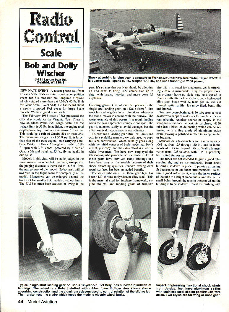
A recent phone call from a Texas Scale modeler asked about a competition event for monster multi‑engined airplanes that have always exceeded the AMA's 40‑lb. limit for Giant Scale (Event 514). Good news: the February 1988 issue of MA presented the official schedule for the Virginia Nats — they have added an event, FAI Large Scale.
- Weight limit: 55 lb.
- Total engine displacement top limit: 61 cu. in. (for example, a pair of Quadra 50s or three 35s).
- Maximum wing area: 538 sq. ft.
- Static judging: same as other FAI entrants, except judging distance is increased to 165 ft. from the nearest part of the model.
- Flight score: no bonuses for model complexity; maneuvers may be enlarged beyond the limits set for smaller FAI models.
Imagine a model 18 ft. span, 3 ft. chord, powered by a pair of Quadra 50s and weighing 55 lb., flying legally at the Nats. The new event brings U.S. competition up to date for larger, heavier, more powerful airplanes.
Landing Gear
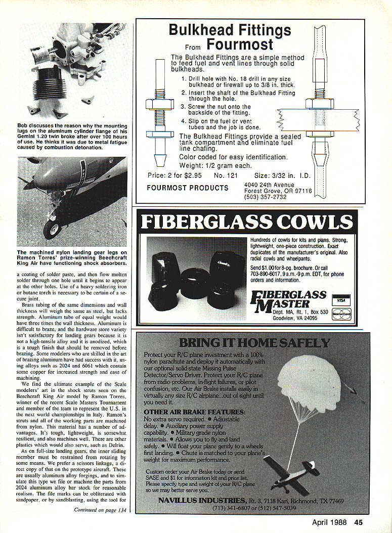
One of our pet peeves is the single‑strut landing gear on a Scale aircraft that wobbles and wiggles in all directions whenever the model moves in contact with the runway. The worst examples occur on rough landings when the gear approaches collapse. To produce a landing gear strut that looks and acts scalelike, copy full‑size construction: don't invent — just copy. The extra effort is a worthwhile investment.
I have used the telescoping‑tube principle on six models. These gears have survived many landings and have been easy on the models because of their shock‑absorbing qualities. Smooth taxiing over rough surfaces is an added benefit.
#### Telescoping‑tube construction and materials
- Outer tubes: 4130 chrome‑molybdenum alloy steel (used on full‑size fuselage frameworks, engine mounts, landing gears). Tough and workable with proper tools.
- Cutting: ordinary hacksaw blades wear quickly; use a high‑speed alloy steel blade (32 TPI). 4130 can be filed, bent, slit, brazed, or otherwise worked.
- Sources: local dealers who supply custom aircraft builders, or scrap bins at local airports.
- Finish: 4130 often has a black oxide coating that can be removed with fine‑grade aluminum‑oxide cloth to leave a polished surface for soldering or brazing.
- Standard outside diameters: increments of 1/16" (.062") from .25" through .50"; 1/8" (.125") increments beyond .50".
- Wall thickness: typically .028" to .062"; about .035" is well suited for model landing‑gear use.
Ordinarily the tubes are not intended to give a perfect telescoping fit, so brass bushings are inserted and soldered in place to provide a running fit between outer and inner members. To assure a good solder joint, clean the inner surfaces to a bright smoothness and drill small holes so solder will flow and wet the bushing. Use a heavy soldering iron or a butane torch where necessary.
Brass tubing of the same outside diameter and wall thickness weighs about the same as steel but lacks the strength. An aluminum tube of equal weight would require roughly three times the wall thickness; aluminum is difficult to braze unless you use proper alloys (e.g., 2024 or 6061) and techniques.
#### Shock materials and scissors linkage
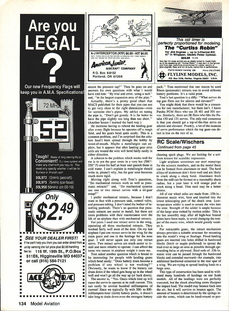
- Nylon (machined nylon) has proven excellent for shock struts: tough, lightweight, resilient, and easy to machine. Delrin and similar plastics are also suitable.
- As on full‑size landing gears, the inner sliding member must be restrained from rotating. A scissors linkage is preferred, copying the prototype. These scissors parts are usually aluminum alloy forgings; on models we file or machine them from 2024 aluminum alloy bar stock for realism.
- Light airplanes sometimes use steel stampings for scissors members; on the model these can be formed from aluminum or thin steel. Hard aluminum alloys do not form well and may crack; annealed aluminum forms better but may orange‑peel. Thin steel may be the better choice for stamped scissors members.
- File marks on machined scissors parts can be removed with sandpaper or by sandblasting.
#### Axles and assembly
- Wheel axles: .156‑in. diameter music wire, bent and inserted into the outer telescoping part of the shock strut.
- Secure the wire with low‑temperature solder after all high‑heat brazed joints are complete (to avoid changing the temper of the music wire).
- For retractable gears, the retract mechanism typically provides mounting structure for wing or fuselage installation.
- For fixed gears, insert the legs into holes drilled in hardwood blocks (birch or maple preferred) to spread the load. The .156‑in. music wire may be extended rearward through hardwood sections to spread landing loads over a larger area.
This construction has withstood many hundreds of landings. The shock‑absorbing struts dissipate much of the impact load; the amount of bounce is determined by the springs inside the struts, which can be hand‑wound or purchased.
#### Ready‑made shock‑absorbing struts Ready‑made struts save time and are adaptable to fixed or retractable gears. Example:
- Impact Engineering struts by W. S. Jerday, Inc.
- Sizes for models from about 3 to 15 lb.
- Body diameters: .375" and .50"; axle sizes: .156" and .312".
- Construction: 6061‑T6 aluminum housing, stainless lower sliding member, music‑wire axles pressed in place; universal installation using 6‑32 setscrews.
- Manufacturer address (as listed): W. S. Jerday, Inc., 2110 Stonehill Ct., Arlington, TX 76012.
Heat treatment and spring forming
A common problem is landing‑gear struts that bend easily after winding the springs. A practical remedy: put the gear struts in a very hot oven (about 500°–550°F) for half an hour and quench them in cold water. This treatment often makes the strut noticeably more rigid. (A metallurgist could explain the exact mechanism.)
Spring making and related techniques were described in our April 1987 column of MA.
Retracts and servos
Questions often arise: do mechanical retracts work as well as pneumatics? Do mechanical systems use one or two retract servos with a tri‑gear setup?
- Preference: mechanical retracts. Pneumatics are easier to install but require a pressure tank, control valve, tubing, and more maintenance over the life of the airplane.
- Servos: for years one retract servo operating all three mechanical retracts worked fairly well. On our last airplane we used two retract servos — one in the wing for the mains and one in the fuselage for the nose gear. Two retract servos are easier to install and more reliable; the extra two ounces is worth the reliability.
- Battery drain: if a wheel is hung up in the well and the servo stalls, the servo will draw stall current (often several hundred milliamperes). With typical 500–800 mAh battery packs, this can drain the battery quickly. Pneumatic systems were sometimes chosen to avoid airborne battery problems, which is a valid concern.
Servos for flaperons and elevons:
- There is no unanimous consensus on a single preferred servo manufacturer.
- Many use top‑of‑the‑line servos from Futaba, JR, or equivalent high‑performance models.
- The only real consensus: use a top‑of‑the‑line servo for flaperons or elevons; subtle performance differences are most detectable by expert flyers.
Four‑stroke engine problems
Scale modelers often conceal powerplants inside close‑fitting cowls or mount them rearward with extension shafts. Two‑stroke engines tolerate this treatment better than four‑strokes. Four‑strokes produce much higher exhaust temperatures, which can cause problems:
- Early experience: a homemade internally mounted aluminum muffler (brazed aluminum) suffered melted brazed joints; droplets of molten aluminum fell inside the cowl and later rattled around.
- Discoloration of plated exhaust tubing and charred wood where pipes contacted balsa or plywood are evidence of excessive heat. Prop blast can supply oxygen that intensifies heating of nearby materials.
#### Cooling, induction air, and detonation
- Baffled air ducts close‑fitting around cylinder fins are still recommended to force cooling air where it does the most good.
- However, a baffle that leaves the carburetor intake exposed to heated air inside the cowl can cause problems: ingestion of hot intake air (around 200°F or above) can contribute to detonation in four‑stroke engines.
- Full‑size aircraft with superchargers use intercoolers (mounted between the supercharger and carburetor) to reduce induction air temperature.
- On scale models with exhaust pipes enclosed within the cowl, ensure sufficient circulation to carry heat away from the pipe, or provide separate ducting to bring cooler air to the carburetor intake.
- Detonation is most likely under load (for example, during a climb) and is audible from the ground as a characteristic clatter.
#### Detection and mitigation
- If detonation is detected from the ground, the safest action is to reduce throttle and land.
- Reset the needle valve slightly richer to cool the engine and prevent further detonation; expect some power loss but improved longevity.
- A tachometer only shows when the engine is peaked; remember the engine will run slightly leaner in the air.
- Tighten the prop nut frequently (after every flight or two) — detonation and backfiring can loosen or wear prop drive hardware (e.g., drive washers with flats).
#### Examples and failures
- Enya .120: detonation caused damage to the prop drive washer; flats in the aluminum drive washer wore away after a year's operation.
- Gemini 1.20 twin: after 100+ hours, a loss of power revealed a fractured aluminum cylinder jacket along a sharply machined corner at the mounting flange. On full‑size, air‑cooled engines this corner always has a large radius; the Gemini jacket lacked this radius and fractured. Only one of four lugs remained intact, preventing complete loss of the head, cylinder, and valves.
- Repair: a later cylinder of 2024‑T351 aluminum alloy with a proper radius was installed; the old liner, piston, and heads were reused where possible, and the engine returned to service.
- Internally the engine showed no wear or carbon/gum buildup after 100 hours while using castor oil as the only lubricant. Still, detonation is a prime suspect in long‑term fatigue failures; four‑stroke engines are expensive and deserve careful treatment.
Contest notes
"I have it from reliable sources that Ed Berton took first in Open Expert and was the Expert overall winner. Shaun Ernst won Sportsman Open, while Rust Smith was the overall winner in the category. Disaster at Disney or not, we all had time (between winch and retriever breakdowns) to share impressions that will make for conversation into the far, far future. Nobody told us until we were there that this was the Thirteenth Annual Tangentiner!"
Transcribed from original scans by AI. Minor OCR errors may remain.

