
Radio Control: Scale
Bob and Dolly Wischer S-221 Lapham Peak Rd. Delafield, WI 53018
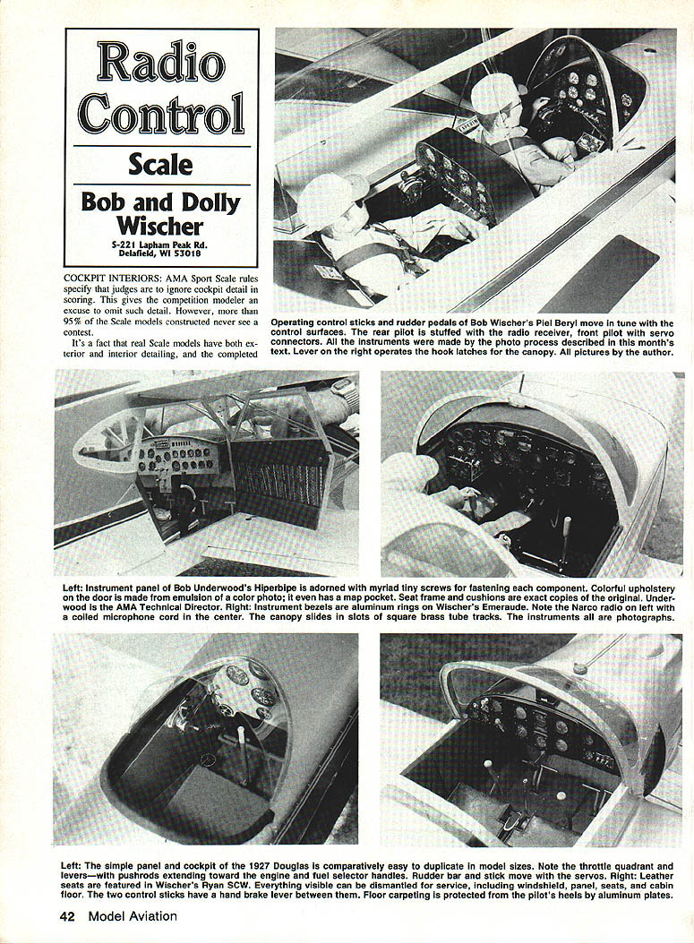
Cockpit interiors
AMA Sport Scale rules specify that judges are to ignore cockpit detail in scoring. This gives the competition modeler an excuse to omit such detail. However, more than 95% of the scale models constructed never see a cockpit.
Real aircraft have both exterior and interior detailing, and a completed cockpit is a serious concern of the dedicated scale modeler — reproducing the airplane with nothing omitted. Pride of workmanship also contributes to the urge to reproduce every possible detail. Of course this leads to the old adage that a scale model is never really finished: there are always missing details.
With 20-plus scale models currently in our collection, the real problem in detailing an aircraft's interior is lack of information. Photographs alone can be helpful, but accuracy isn't satisfied without at least a few hard dimensions to establish proportions. Most three-view drawings are somewhat lacking in this respect. The best source of information is privileged access: climb into the cockpit with a camera and a tape measure. Pencil and pad are also requirements.
Memory alone doesn't serve us well unless we're blessed with photographic memories to help reproduce parts later. In our own efforts at scale modeling, crude pencil sketches with dimensions are the last word in getting everything in the proper position and correct size. Using a steel tape measure on the full-size aircraft will often reveal inaccuracies even in respected three-view drawings. Given the opportunity, we prefer to obtain dimensions piece by piece; the cockpit interior is no exception.
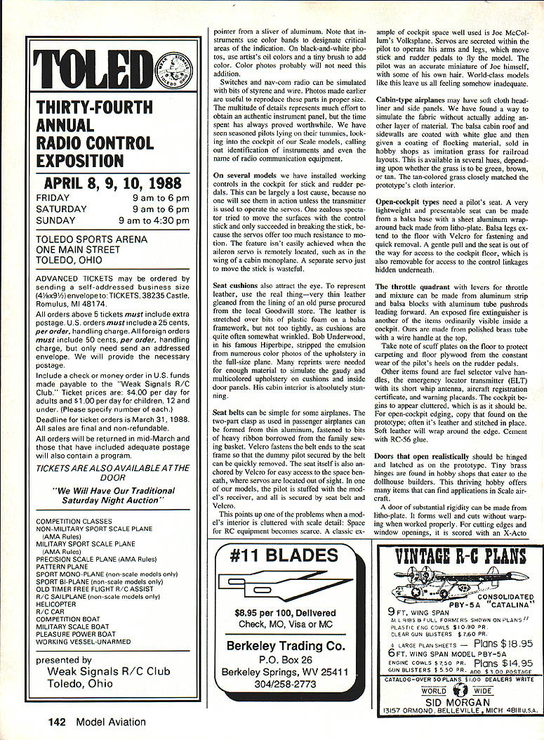
The single most visible item in a cockpit, and the focal point of intense viewer interest, is the instrument panel. Instrument faces can be purchased depending on model scale; sometimes they are approximate representations of the real panel. Our preference, whenever possible, is to gain access to the cockpit and photograph each individual instrument as well as switches, navigational aids, and other items.
Photographing instrument faces
The camera we use is an ordinary 35mm single-lens reflex. Start with a known full-size dimension — for example, a three-inch-diameter instrument. At the chosen scale ratio, the instrument face on the model should be the corresponding scaled diameter (for example, .60 in.).
Procedure:
- Place a piece representing the instrument (such as a cardboard disc) on ground glass (waxed paper) with the camera's open-back film position set and the exposure bulb set so the shutter will remain open.
- Aim the lens at the three-inch-diameter object and focus the lens.
- Move the camera toward or away from the object until the image on the ground glass measures the scaled diameter (for example, .60 in.). This helps with viewing and composition.
- With the back of the camera shielded from extraneous light, measure the distance from the object to some fixed point on the camera, such as the tripod socket.
- Make a wood strip of that length and fasten the tripod socket to it with a 1/4-20 screw (standard cameras). This maintains the correct distance when focusing the lens.
With the end of the wood strip resting against the panel beneath an instrument dial, the image will be centered within the frame of each photo in the roll. Just wind the film and shoot — no need to look through the viewfinder. The image on the film will be the exact scale for every exposure.
After developing the film, have contact (proof) prints made of the roll for ready-made instrument faces. Our favored film is Kodak Tri-X. This system provides prints of the highest possible definition because there are no enlargement steps in the process. It requires a camera lens with quite close focusing capability and can be used on all model scales up to and including 1/4-scale. One thing to remember is that a three-inch dial in 1/4-scale may be larger than a 35mm film frame.
For color prints from a local processor the camera must be placed farther from the panel, because the prints are typically enlarged about 3.7 times the original negative size. Continuing the earlier example, if the model instrument face should be .60 in. on the model print, the image on the ground glass or waxed paper should be .60 × 3.7 = 1.6 in. diameter. Measure the camera-to-subject distance for this image size, then load the camera with film and take the photos in the airplane at that distance, using the wood strip (or a steel tape) for spacing. The wood strip will show up in every print and will underline the instrument.
To minimize direct reflections in the glass covering the instrument face, lower the camera slightly so the line of sight isn't at right angles to the glass. Using the camera at a slight angle helps; paint the wood strip flat black and wear dark clothing to keep the photographer out of reflections. Taking photos while standing outside the cockpit also helps. Reflections can be eliminated by using a polarizing filter.
For either the black-and-white or color systems described, a wide-angle lens is preferred. We employ a 35mm focal length that has an optimum focusing distance of nine inches. For the color process, the wide-angle lens brings the camera close to the panel so that seat backs in the airplane don't interfere.
Making the instrument panel
The panel itself can be made from 0.062-in. styrene sheet with holes cut for the instruments. We have been painting panels with the same black crinkle spray can for ten years.
Some instruments have a bezel surrounding the face. Make bezels from switch tubing or from strips of aluminum wrapped around a dowel. Glue the bezel into the hole, and glue the instrument face (photo print) into the back of the panel. If the prints were made on glossy paper, there is an immediate illusion of a glass face. To enhance appearance, clear plastic sheet can be sandwiched between face and panel, or set plastic discs into the bezels.
To add depth to an instrument face, make a pointer from a sliver of aluminum. Instruments often use color bands to designate critical areas of indication. On black-and-white photos, use artist's oil colors and a tiny brush to add color. Color photos probably will not need this addition.
Switches, radios and controls
Switches and nav-com radios can be simulated with bits of styrene and wire. Photos made earlier are useful to reproduce these parts in proper size. Although the multitude of details represents much effort, the time spent is worthwhile — seasoned pilots have lain on their tummies looking into our cockpits, calling out instruments and even the names of radio equipment.
On several models we have installed working controls in the cockpit for stick and rudder pedals. This can be a lost cause, because no one will see them in action unless the transmitter is used to operate the servos. One zealous modeler tried to move the surfaces with the control stick and only succeeded in breaking the stick, because the servos offer too much resistance. The feature isn't easily achieved when the aileron servo is remotely located (for example, in the wing of a cabin monoplane). A separate servo just to move the stick is usually wasteful.
Cabin-type airplanes may have soft cloth headliner and side panels. We have found a way to simulate the fabric without adding another layer of material: coat the balsa cabin roof and sidewalls with white glue, then apply flocking material (sold for railroad layouts) while tacky. Flocking is available in several hues; the tan color closely matches many prototypes' cloth interiors.
Seats, upholstery and small details
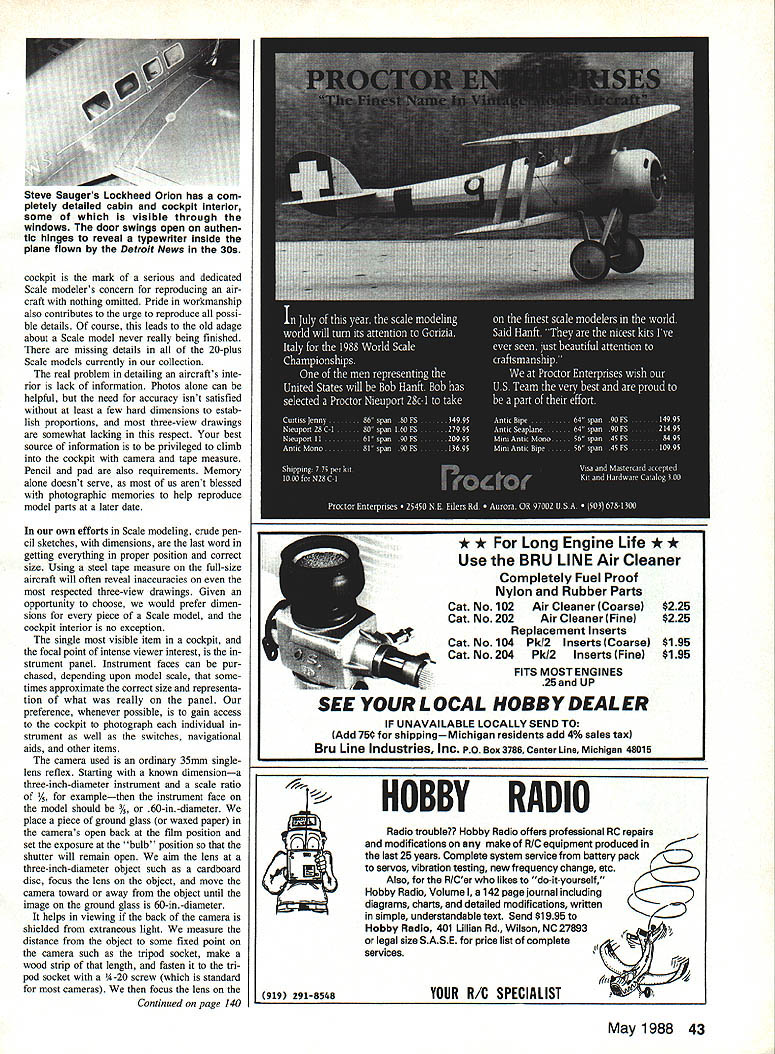
Seat cushions attract the eye. To represent leather, use the real thing — very thin leather gleaned from the lining of an old purse. Stretch the leather over bits of plastic foam or a balsa framework, but not too tightly, as cushions are often somewhat wrinkled. Bob Underwood, in his famous Hiperbipe, stripped the emulsion from numerous color photos of the full-size upholstery to gather material for cushions and door panels. His cabin interior is stunning.
Seat belts can be simple. Two-part passenger-clasp assemblies can be formed from thin aluminum and fastened to bits of heavy ribbon from the sewing basket. Velcro fastens the belt ends to the seat frame so the dummy pilot secured by the belt can be quickly removed. Anchor the seat itself with Velcro for easy access to the space beneath, where servos are located. In one model, the pilot houses the receiver and all is secured by seat belt and Velcro.
This points up one problem: when a model's interior is cluttered with scale detail, space for RC equipment becomes scarce. A classic example of clever space use is Joe McCollum's Volksplane: servos are secreted within the pilot to operate his arms and legs, which move control surfaces. The pilot was an accurate miniature of Joe himself, even with some of his own hair.
Open-cockpit types need a pilot's seat. Make a very lightweight seat from a balsa base with a sheet aluminum wrapper around the back formed from litho-plate. Balsa legs extend to the floor and use Velcro for fastening and quick removal. A gentle pull removes the seat for access to the cockpit floor and hidden control linkages.
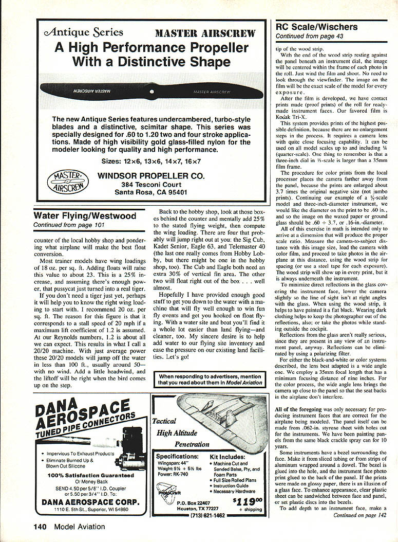
The throttle quadrant with levers for throttle and mixture can be made from aluminum strip and balsa blocks with aluminum tube pushrods. An exposed fire extinguisher can be made from polished brass tube with a wire handle at the top.
Take note of scuff plates on the floor to protect carpeting and plywood from the pilot's heels. Other common items include fuel selector handles, the emergency locator transmitter (ELT) with its short whip antenna, and the aircraft registration certificate often mounted in a stitched leather holder. Soft leather will wrap around edges; cement with RC-56 works well.
Doors, windows and finishing
Doors that open realistically should be hinged and latched as on the prototype. Tiny brass hinges for dollhouse builders are useful and readily available.
A door of substantial rigidity can be made from litho-plate. It forms wall and door without warping when worked properly. For cutting edges and window openings, score the plate with an X-Acto bladed only partway through, then bend along the score line to crack cleanly. Touch up burrs with a fine file.
For sharply formed edges, clamp the sheet between two hardwood blocks with the edge extending. Push the protruding edge with another wood block and it will bend sharply into a 90° angle. Brace the door internally with balsa, cemented to the aluminum with RC-56 for a permanent and somewhat elastic bond.
Window frames are made from strips of litho-plate and provide a secure mounting for clear acetate or Plexiglas windows. Litho-plate aluminum is primed for painting with automotive finishing materials; we use Ditzler lacquer primer surfacer DZL-32 light gray. The metal can then be finished with any type of paint, including dope, with no problem of peeling.
Notable example
The most complete cockpit we have seen was by Mick Reeves in his Fournier RF-4. Built to 1/4-scale, the model is large enough to reproduce detail with great authenticity. The instrument panel is an all-time classic: instruments are operational, the turn-and-bank indicator shifts when the model is tipped, and blowing into the pitot tube makes the airspeed indicator needle swing authentically. The rudder pedals have wear marks from pilot shoe soles.
The dummy pilot has hair from Mick's head, and his earphones actually pick up BBC signals. Every detail is reproduced to exact scale and in the proper location, the result of concerted effort over a long period. Mick and the Fournier were rewarded in 1978 with a well-deserved FAI World Championship. Future competitors will be measured against that immaculate scale model.
Transcribed from original scans by AI. Minor OCR errors may remain.

