
Radio Control: Scale
Joe Tschirgi 1841 Whitestone Santa Ana, CA 92705
STRANGE AIRCRAFT are known to emerge from my workshop. Model Aviation's publisher asked me to write a short piece on RC Scale models, noting that I was "... known for building strange models." I prefer to say I build models of strange aircraft, and I agreed to describe experiences with some of these — a license to expose a few favorite prejudices and misconceptions as well.
I've always favored WW I–era prototypes because they are simple, and because the variety of configurations is fascinating: monoplanes, biplanes, triplanes, quadraplanes, landplanes, floatplanes, flying boats, amphibians, and even twin‑engined oddities (how about a twin‑engined quadraplane with a biplane tail?). With a little research it's easy to find prototypes that experienced modelers can identify. For competition use, both the AMA and FAI rule books describe procedures for getting self‑drawn three‑views approved, and most Scale judges allow educated guesswork on colors and markings for obscure prototypes.
Below I describe two WW I–era prototypes I modeled: the Dufaux and the Brandenburg W.18. Both were sole prototypes in their day and illustrate construction, propulsion, cooling, flight trimming, and lessons learned.
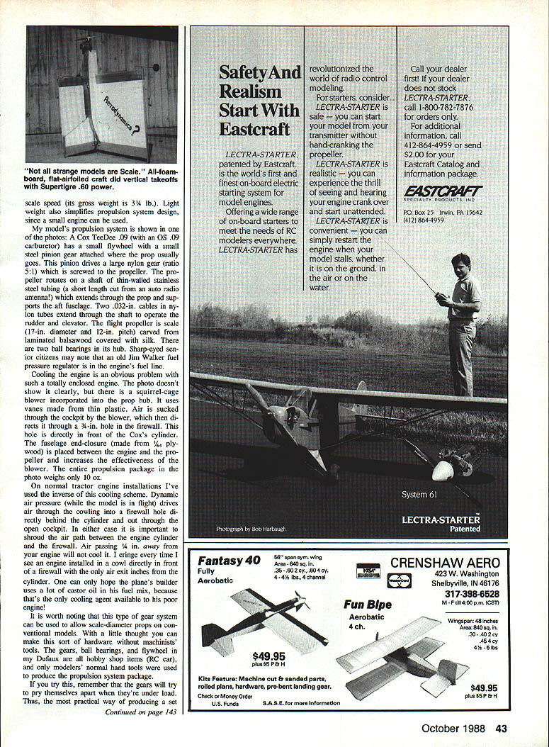
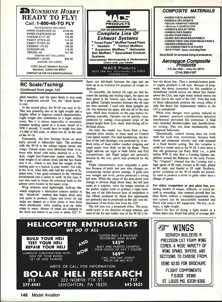
Dufaux (circa 1916)
The Dufaux first flew in early 1916. It was a very simple, conventional two‑place, single‑bay biplane — except for one bizarre feature: the engine was located behind the crew and the propeller was aft of the wings' trailing edges. A fixed hollow tube (upon which the prop rotated) supported the aft fuselage and tail assembly. Pilot and gunner sat side‑by‑side in the nose.
Model data:
- Scale: 1/6
- Span: about 52 in
- Wing area: about 830 sq. in.
- Gross weight: about 3.5 lb
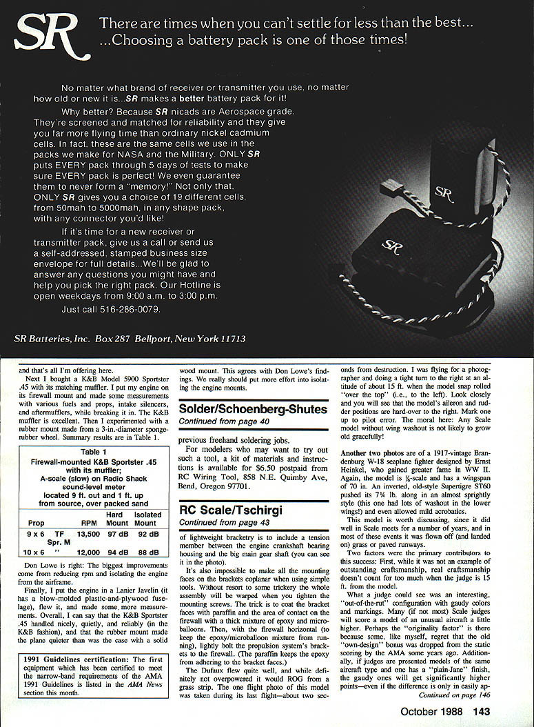
The model was built lightly to approximate scale speed and to allow use of a small engine. The propulsion package:
- Engine: Cox TeeDee .09 (with .09 carburetor)
- Drive: small steel pinion on the engine flywheel driving a large nylon gear (5:1 ratio) screwed to the prop
- Prop shaft: thin‑walled stainless steel tubing (short length cut from an auto radio antenna) extending through the prop and supporting the aft fuselage
- Controls: two .032‑in. cables in nylon tubes routed through the shaft to operate rudder and elevator
- Propeller: scale 17‑in. diameter, 12‑in. pitch, laminated carved balsa covered with silk; two ball bearings in the hub
- Ancillary: old Jim Walker fuel pressure regulator in the fuel line
- Entire propulsion package weight: about 10 oz
Cooling the engine in such an enclosed installation is a challenge. I incorporated a squirrel‑cage blower into the prop hub, with vanes made from thin plastic. The blower sucks air through the cockpit and directs it through a 3/16‑in. hole in the firewall, directly in front of the Cox cylinder. A 1/8‑in. plywood fuselage end‑closure between engine and propeller increases blower effectiveness.
On tractor installations I use the inverse scheme: dynamic pressure forces air through the cowling into a firewall hole behind the cylinder and out through the open cockpit. In both cases it is critical to shroud the air path between the engine cylinder and the firewall — air passing 3/16 in away from the engine will not cool it.
Flight and lessons:
- The Dufaux flew quite well and would ROG (rise off ground) from grass. The model suffered a fatal crash during a tight turn at ~15 ft altitude: it snapped into a vertical "over the top" and flipped left while control surfaces were hard‑over to the right. Pilot error; the moral is that any Scale model without wing washout is unlikely to grow old gracefully.
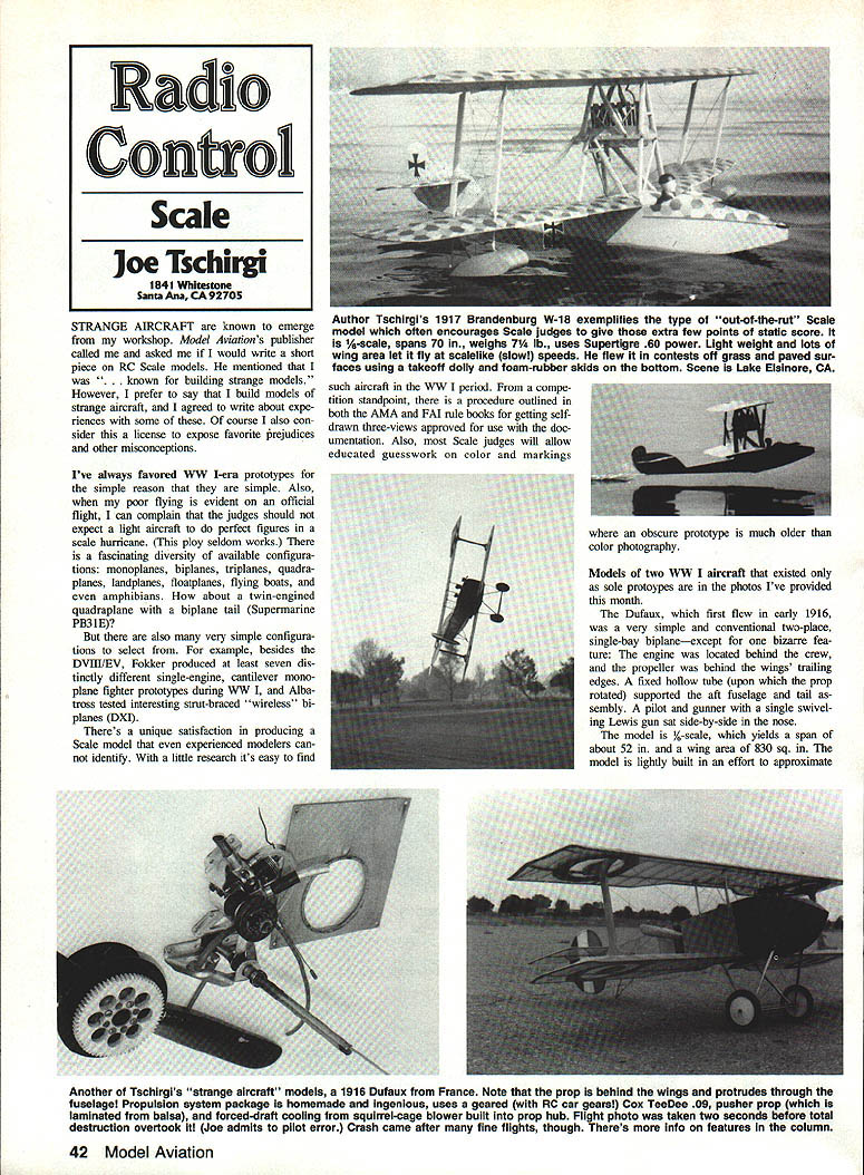
Brandenburg W.18 (1917) — seaplane fighter by Ernst Heinkel
The Brandenburg W.18 was a 1917 seaplane fighter designed by Ernst Heinkel. My scale model has a 70 in wingspan and used an inverted old‑style SuperTigre 61 engine. The model was long and relatively sprightly (with significant washout in the lower wings) and permitted mild aerobatics. It also did well in Scale meets and was often flown off grass or paved runways.
Why it scored well:
- Judges often favor originality, unusual aircraft, color, and markings. Presentation matters — "decal factor" is real.
- The model's design and construction emphasized flying qualities rather than only appearance.
- Light weight and generous wing area helped produce scale‑like slow flight.
Weight and structure:
- It is almost impossible to truly simulate full‑scale landing speed in a 1/2‑scale model; to do so the model would need to weigh far less than practical (on the order of 1/1,000 of full scale).
- The early box fuselage style is inherently light.
- Cabane struts: fabricated from 3/32‑in. brass tube faired with balsa and attached to a 3/32‑in. maple box‑frame engine mount. The total weight of cabanes plus box frame was about 9 oz — lighter than a typical 1/4‑scale landing gear.
- The 1/4‑in. brass tube used elsewhere is light, resists vibration, and is easier to work; it also served as a conduit for electrical leads to aileron servos in the upper wing.
Wing construction (sliced‑rib style):
- Shape upper and lower rib caps on a form (mine is bent from sheet aluminum).
- Soak 1/8‑in. sq. balsa strips in water, clamp them to the form, and bake at about 325°F to bend.
- Build full‑depth spars between the caps, using a built‑up I‑section for weight reduction.
- Assemble by laying the bottom rib caps between the leading and trailing edges, glue spars to bottom caps, add top caps, then insert upright members between caps (I used three uprights per rib: one between spars and one aft of the rear spar). Mass‑produce uprights by slicing cross‑grained strips from 1/8‑in. sheet.
Landing gear and land operations:
- For land operations the model used a four‑wheeled dolly (similar to Control Line Speed rigs). For land touchdowns the hull bottom was protected by 1/4‑in. foam rubber weather stripping and small music‑wire skids glued to the hull. These skids are legal in AMA and FAI competitions and give a very quick stop, much to the amusement of flight judges.
Trim and propwash issues:
- The model exhibited pitch and yaw trim changes with power settings. When glide trim was straight and level, adding power produced a diving left turn.
- Cause: propwash effects, not merely thrust‑line displacement relative to the CG. Propwash swirls in the direction of prop rotation; most of the fin and rudder area on the W.18 is below the thrust line, so a normal‑rotation pusher produced a left turning moment.
- Corrective adjustments: downthrust (moves thrust line further above the CG) and right thrust (moves thrust line to the right of the CG). Note these adjustments can have counterintuitive effects if only thrust‑line geometry is considered.
- Final cure: throttle/rudder and throttle/elevator mixing, implemented mechanically with compound bellcranks. Theoretical concerns exist because thrust and propwash vary with airspeed, but in practice the variation was small and mixing worked well to reduce trim changes.
Anecdote: I once knew a pilot who claimed his Loening amphibian had wildly varying speeds for different regimes — an example that, for some aircraft, power changes produce climb/glide effects rather than pure speed changes.
Practical construction tips and notes
- Gears and mounting:
- When using gears under load they will try to pry apart. Glue bearings in place with a structural adhesive and epoxy the gears onto the pins.
- Support the prop shaft with a tube or bushings so prop load cannot pull the shaft out of the fuselage.
- Use nylon gears where possible — they are lighter and quieter.
- Bracket mounting trick:
- It is difficult to make all mounting faces coplanar with simple tools. Coat bracket faces with paraffin, coat the firewall contact area with a thin mixture of epoxy and microballoons, then bolt the assembly lightly to the firewall while horizontal. The paraffin prevents the epoxy from adhering to the brackets and the epoxy/microballoon fills gaps so the assembly cures without warping.
- Lightweight bracketry:
- Include a tension member between the engine crankshaft bearing housing and the main gear shaft to help carry loads.
- Cooling:
- Shroud the air path between cylinder and firewall; direct airflow must pass over the cylinder to be effective.
- Materials:
- Small‑engine installations and clever gearing allow use of scale‑diameter props without heavy engines. Many gear, bearing, and flywheel parts are available from RC car suppliers and can be assembled with normal modeler hand tools.
Final thoughts
For competition or pure enjoyment, producing models of unique, unusual, or weird aircraft is very rewarding. Many unusual aircraft that flew without computer‑augmented controls can be successfully modeled and flown with today's RC gear. The key, as always, is light weight.
Don't let fear of a light model in a breeze deter you. Pilots of average ability can handle models with wing loadings around 8 oz per sq. ft. in winds exceeding the models' minimums — evidence is visible at any slope‑soaring site. Let's get out of the WW I fighter rut!
A life‑scale example: a full‑scale span of 70 in, weighing about 7 lb and using Supertigre .60 power, will fly scale‑like at slow speed when built light and with lots of wing area. It can operate from grass or paved surfaces with a takeoff dolly and foam‑rubber skids on the bottom.
Joe Tschirgi 1841 Whitestone Santa Ana, CA 92705
Transcribed from original scans by AI. Minor OCR errors may remain.

