
Radio Control: Scale
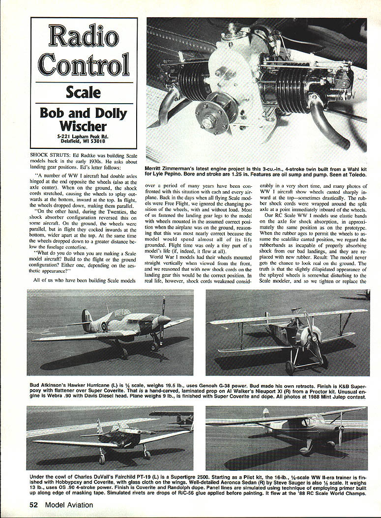
Shock Struts
Ed Radtke, who was building scale models back in the early 1930s, asks about landing gear positions. Ed's letter described two common historical arrangements:
- On many World War I aircraft the double axle was hinged at the end opposite the wheels (and sometimes at the axle center). On the ground the shock cords stretched, causing the wheels to splay outwards at the bottom and inward at the top. In flight, the wheels dropped down and became parallel.
- In the 1920s some aircraft used a reversed shock-absorber configuration. On the ground the wheels were parallel, but in flight they cocked inward at the bottom and wider apart at the top, and the wheels hung further below the fuselage centerline.
What should a scale modeler do — build to the flight configuration or the ground configuration? The answer is: either, depending on the desired aesthetic and the prototype’s typical appearance.
In the days when most flying scale models were free flight, modelers usually fixed the landing gear in the position correct for the airplane at rest, reasoning that the model would spend almost all of its life on the ground. World War I models were often built with the wheels vertical when viewed from the front, assuming new shock cords would hold that position. In real life, though, the rubber shock cords often weakened quickly and many photos show wheels canted sharply inward at the top. On scale RC World War I models we use elastic bands for axle shock absorption in approximately the same position as on the prototype. As the rubber ages and the wheels assume the canted position, modelers typically replace the rubber to retain shock absorbency, so the model rarely shows the slightly dilapidated look of stretched shock cords.
After World War I, oleo shock struts became common and the relationship of wheel position in the air and on the ground changed more dramatically. Properly serviced oleos tend to leave wheels near vertical on the ground, though often cambered slightly outward at the top by a few degrees.
Camber and Toe-In
- Camber angle (wheels canted slightly outward at the top) helps stability.
- Toe-in (viewed from above, the front of the tires are a little closer together than the rear) helps reduce ground-looping and aids straight tracking on takeoff and landing.
Scale toe-in is desirable on tail-dragger models for the same reasons it helps full-size airplanes. However, toe-in can affect appearance: if a tail-dragger is towed backward, toe-in causes the wheels to spread away from the airplane centerline and look ungainly. There are numerous photos showing this condition on full-size aircraft moved rearward before photography; contest judges may mistakenly consider such positions normal.
For greatest realism, a model’s wheels should also move vertically when load is removed during takeoff.
Vertical Motion and Telescoping Struts
Many modern scale models simulate oleo action without full-scale oleo complexity. Common practice is to use telescoping struts with internal springs to absorb landing shocks. These systems give some vertical travel so the wheels drop down slightly on takeoff and rise under load on the ground. Full-size airplanes can show several inches of travel; model travel is necessarily less but can be scaled to look right.
Springs alone store energy and tend to produce bouncy landings, unlike an oleo where oil forces through an orifice to damp motion. A secondary problem is bottoming-out on hard landings when the spring compresses to its solid length or the strut reaches its mechanical limit, often producing an audible "click" as metal meets metal and then another as the spring rebounds. To reduce this, modelers sometimes use a smaller rebound spring at the bottom of the strut, enclosed within the outer tube — an idea borrowed from full-size practice. Properly designed model struts travel a reasonable scale distance and look correct both on the ground and in the air.
Single-Strut Landing Gear
Single-strut landing gear, common on many modern aircraft, presents a different challenge. Because many model landings occur nose-low, typical model gear legs include a torsion spring formed in the wire near the top. This allows the landing gear leg to swing rearward, absorbing shock in two directions. If a scale modeler has improved flying and landing technique sufficiently, the torsion-spring arrangement will absorb most landing shocks without requiring complex oleo mechanisms. Nonetheless, care in design and testing is still needed to avoid damage on very hard landings.
FAI Rule Changes
At the 1987 FAI plenary session in Paris there was a dramatic rule change: the top limit on engine displacement for scale models was removed entirely. That blanket removal was later reconsidered. The FAI Bureau, at its subsequent annual meeting, placed a top limit on total displacement of 80 cc (4.8 cu. in.). This is a generous limit compared with the past. For example, a four-engined model could now use 1.2-cu.-in. engines on each nacelle. The real limiting factor for FAI scale is still the 15.4-lb weight limit; it is hard to imagine a 15-lb airplane needing the full 4.8-cu.-in. allowance or, say, a pair of Quadra 35s.
Sound Limits and Measurements
The FAI Scale Subcommittee has suggested adopting a 90 dB upper limit at two meters, similar to the AMA objective. This proposed limit is lower than the current FAI limit of 98 dB. The proposal specifies measurement over a hard surface, which is impractical for many clubs that do not fly from hard surfaces except at major contests. It would be preferable to either measure sound while the model is suspended above a surface or not stipulate a specific surface type. None of the local clubs in our area operate from a hard surface.
Three of our club members have purchased sound level meters to monitor noise. The inexpensive unit sold by Radio Shack (catalog No. 33-2050) currently retails for about $29.95 and has the following characteristics:
- Microphone pickup with a top reading of 126 dB.
- Fast/slow response options to reduce needle fluctuation on sharp impacts.
- Selectable A and C weighting characteristics for sensitivity in ranges most relevant to human hearing.
- Measurement sensitivity commonly quoted in the 500 to 10,000 Hz range.
- Manufacturer-stated accuracy of ±2 dB at 114 dB; our comparisons indicate even closer agreement.
We believe AMA objectives should not require expensive equipment or unrealistic testing conditions if they expect wide compliance. Most important, the fact that several club members have invested in meters shows a serious commitment to reducing noise. At our field, the nearest neighbor is almost a half mile away; one member has spoken with nearby residents and confirmed that noise is not presently a problem. Our meters serve as insurance.
Noise Reduction and Mufflers
Over recent years there has been a marked reduction in noise from scale models. In the past, heavy and powerful scale models at national contests were often loud because builders hesitated to use effective mufflers that slightly reduce performance. With the FAI displacement lid removed, there is no longer an excuse for flying without a good muffler in FAI-class models. Using effective mufflers and proper tuning can significantly reduce noise while maintaining acceptable performance.
Transcribed from original scans by AI. Minor OCR errors may remain.

