
Radio Control: Scale
Don Srull 941 Kimberwicke Rd. McLean, VA 22101
PROGRESS has been made in the state of the art of Scale modelling at an almost unbelievable pace during the last 10 to 15 years. Walking down the flight line at any large Scale RC fun‑fly or major Scale contest these days can be a real experience. It's enjoyable for the spectators and intimidating to the contestants!
The craftsmanship, precision, and daring of today's Scale modelers are truly amazing. Any Scale subject seems to be within easy reach, no matter how difficult or complex; and the scalelike finishes, level of detail, and overall scale appearance achieved by so many modelers would have been difficult to imagine only a short time ago.
It does seem as if Scale modelers are fast approaching the ideal of creating full‑size aircraft which have been magically shrunken down to model size. Luckily, we're not there yet, and many tough and interesting challenges remain.
The Zero's challenge
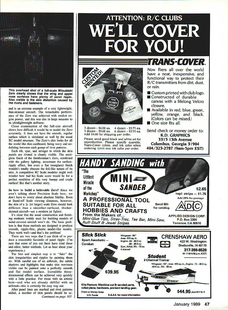
One area where most of us still have difficulty is simulating the ripples in the surface of aircraft covered with light‑gauge metal. This is only a problem for a particular group of aircraft, but a few of these happen to be very popular Scale model subjects. Each time I visit the Smithsonian Air and Space Museum here in Washington, D.C., I eventually wind up in the World War II gallery looking over the Mitsubishi A6M2 — the infamous Zero.
The Zero is a commonly modeled full‑scale aircraft (for good reasons), and is an extreme example of a very lightweight, thin‑skinned aircraft with remarkable performance. The Zero achieved modest engine power due in large measure to its ultralightweight airframe. Close examination of the full‑size aircraft shows why it would be difficult to model. The Zero does not have a smooth, regular surface that can be simulated well with the usual R/C model structure. The Zero's skin looks more like thin cardboard, being wavy and undulating between groups of rivet patterns; rib, spar and stringer skin panels riveted together are clearly visible. The semi‑gloss finish on the Smithsonian's Zero combined with the gallery lighting accentuates the surface‑ripple effect. A flat, non‑glare finish wouldn't totally obscure the foil‑like nature of its skin.
A competitive R/C Scale modeler might well wonder: would a perfect rendition with a very bumpy, crude surface get a bad Scale score? That's another story. Since we're not talking about Precision Scale we don't have to worry about absolute fidelity. At stand‑off Scale viewing distances, however, the skin of a larger‑scale Zero should look different than a smoother‑surfaced, thicker‑skinned aircraft — say, a modern jet fighter. It's clear the usual construction and finishing methods widely used for building metal‑covered models won't solve the basic problem. Methods designed to produce smooth, ripple‑free, plastic‑model‑like results work well — and that's the problem.
Methods to simulate panel ripple
Two ways to think about producing a reasonable facsimile of panel ripple are described here. I'm sure some of you have tried other or better methods; let us hear about your experiences.
1) Painting (airbrush trompe l'oeil)
- The simplest way to fake skin irregularities and ripples is by painting. Careful use of an airbrush with subtle shadows and highlights can make skin waviness visible; it can be painted onto a perfectly smooth, flat model surface. Incredible three‑dimensional effects can be achieved.
- After panel lines are marked and rivet patterns added, select a number of skin panels for subtle shading. The keyword here is "subtle." Don't do all panels, and don't overdo it.
- Use two colors derived from the basic aircraft finish: add a little white for highlights and a little black for shadows. Experiment first on scrap material before attacking the model. Spray the shadows first, then add the highlights. Remember: go easy, and don't overdo it.
2) Scale substructure with thin flexible skin
- This method requires the model substructure supporting the skin to be more or less scale. The model is then covered or skinned with a somewhat flexible material which does not totally hide the supporting substructure. Major bulkheads, stringers, ribs, and spars in the model should be located in scale positions wherever possible. It's usually a good idea to follow the full‑scale prototype structural layout anyhow when scratch‑building a model rather than re‑engineering a perfectly good full‑scale airplane design.
- Rather than using a relatively stiff balsa skin (typical balsa stock would be firm 1/32 in. or 3/64 in.) to sheet or plank the model, use a stronger but more flexible covering material. The skin should flex and distort slightly and make the internal structure visible — like on the prototype Zero. The "starved horse look" which we usually work so hard to avoid is just the thing we're trying to achieve in this case!
- The two materials I have used successfully are 1/64 ply and 1/64 balsa:
- 1/64 ply: very good tensile strength and some flexibility. Best suited for larger‑scale models and easiest to use in large pieces on surfaces devoid of compound curves (for example, wing skins).
- 1/64 firm balsa (or well‑sanded 3/64 soft balsa): well suited to small‑ to moderate‑scale models (1/3‑ and 1/4‑scale), and easy to apply to compound or high‑curvature surfaces. Being more flexible, it will tend to sag and ripple more than 1/64 ply.
- The balsa skin will require a layer of lightweight fiberglass cloth after it is attached to the framework. This provides needed strength to the balsa and makes the surface hard enough to finish. The standard practice of edge‑gluing balsa sheets and sanding to a smooth finish before attaching to the framework still applies.
- Even when the thin‑skin structure is used, add a final touch of panel ripple with an airbrush for that authentic look.
Now, let's hear it for those wrinkled‑skin Zeros!
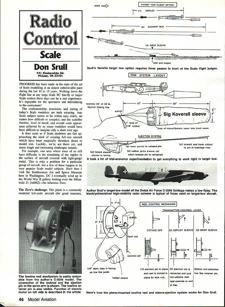
Target tow option
One of the least‑seen and most interesting flight options suitable for a number of Scale aircraft subjects is the target tow. Many military and training aircraft dating back to the Thirties were pressed into service during WWII to tow banners and sleeve targets for ground‑to‑air and air‑to‑air gunnery practice.
A nice plus is that most target‑tow airplanes sport interesting and distinctive — if not garish — color schemes ideal for Scale model use. Properly done, target tow adds an unusual and highly visible flight option to a Scale modeler's repertoire.
Typically, three sequential passes in front of the flight judges are required. The target sleeve is usually carried internally in the aircraft, or within an externally mounted pod. The sleeve is typically one‑half to three‑quarters the length of the towing aircraft and should be towed at a distance of about 10 to 20 times the length of the towing aircraft.
Procedure:
- After deploying the sleeve while flying at cruise speed and medium altitude, make a straight flyby at low altitude (50 to 60 ft.) to simulate a ground‑to‑air gunnery run.
- Then make a low‑altitude pass (10 to 20 ft.) into the wind and parallel to the runway just beyond the landing area. The target sleeve and towing cable are dropped here. Calling the drop and performing it just as the model passes in front of the judges can make a good impression.
- Do not drop the sleeve and line onto the runway — the 50–75 ft. of tow cord can become entangled in the prop of a landing model, usually the tow model.
Basic requirements for the tow mechanism:
- Hold the folded sleeve and the reel of tow cord securely until released.
- On command, eject the sleeve and unreel the full length of tow cord.
- On command, release the tow cord from the reel.
There are many ways to accomplish these items. In my Swiss target‑tow model, the C‑3506 Schlepp, one servo was used for all tow functions. By trial and error I learned a few things that may help others who want to try a tow system.
Target sleeve material:
- Use a lightweight, very springy material that can be folded or compressed into a small space (about 1 x 2 x 3 in.) and which will, when released, tend to spring out to its original tubular shape.
- The material should be unaffected by moisture. Silk worked OK when perfectly dry, but in light drizzle it became a soggy ball and would not unfurl.
- I had luck with Sig's Koverall polyester covering material. I believe the lightweight Dacron cloth used by sailmakers to construct spinnakers would be ideal.
- Full‑size Schlepp sleeves are Dayglow Red or Orange.
Reel and mechanism:
- The reel spool can be built up of hard balsa and 1/8" plywood and made removable as a unit, servo and all.
- Operate the tow servo off an auxiliary channel on the transmitter. In my setup the auxiliary lever is:
- Center position for takeoff
- Full Up to deploy the sleeve
- Full Down to drop the sleeve and tow cord
- Use some form of braking to prevent the reel from overspeeding and tangling. In my model a small electric motor (taken from an old large servo) is normally shorted across its brushes and acts as an electric brake when the sleeve deploys. The motor slows the unwinding reel.
- The same motor can assist rewinding the tow cord after a flight. By removing the shorting plug from the motor leads and connecting a single C‑cell Ni‑Cd to the motor, the reel turns slowly and makes rewinding the 50 ft. of Dacron tow cord easy. The system is lightweight, convenient, and reliable.
If you'd like to try something a little more fun and challenging than the usual bomb or belly‑tank drop, have a go at the target tow option.
Transcribed from original scans by AI. Minor OCR errors may remain.

