
Radio Control: Scale
Joe Tschirgi 1841 Whitestone Santa Ana, CA 92705
Introduction
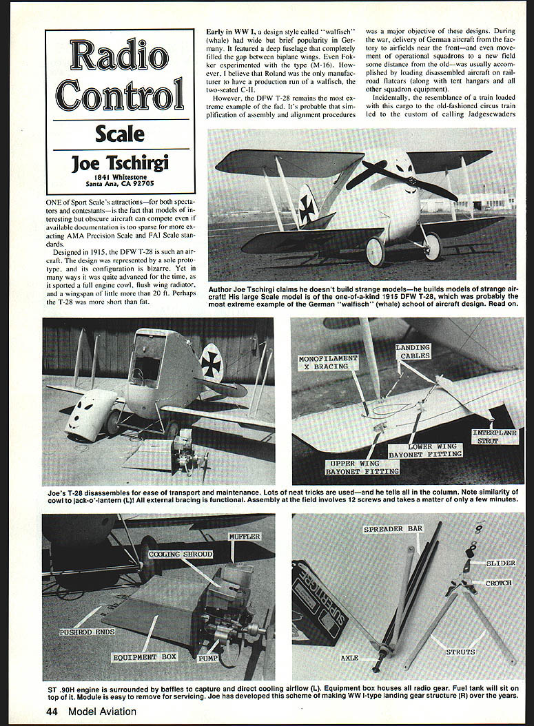
One attraction of Sport Scale—both for spectators and contestants—is that models of interesting but obscure aircraft can compete even when documentation is too sparse for more exacting AMA Precision Scale or FAI Scale standards. The DFW T-28 is such an aircraft: a single-prototype, bizarre-configuration design from 1915 that nonetheless showed several advanced features for its time.
The DFW T-28: background and characteristics
- Designed in 1915 and represented by one prototype.
- Notable features: full engine cowl, flush wing radiator, compact wingspan (little more than 20 ft), deep fuselage filling the gap between biplane wings.
- The style—called walfisch (whale)—had a brief popularity in early WW I Germany. It simplified assembly and alignment for ground crews, useful because aircraft were often shipped disassembled by rail to forward airfields.
- Drawbacks included poor pilot visibility; a photo shows the prototype being taxied with the pilot standing in the cockpit to see over the nose.
Free Flight and RC Modeling of the T-28
Free Flight prototype
In spring 1978 I built a 1.6 in.-to-the-ft Free Flight T-28 powered by a Cox .049 with a 7-inch prop. The model had high drag and was relatively easy to trim for stable flight—high drag often provides damping in pitch and related maneuvers.
Larger RC version (current model)
Encouraged by the Free Flight success, I built a radio-control model at exactly twice the Free Flight linear size:
- Engine: Super Tigre .90H (heat-sink-style cylinder head)
- Propeller: 16 in.
- Span: 65 in.
- Maximum fuselage depth: 20 in.
- Dry weight: ~12½ lb
First flight was nearly a disaster: pitch control was marginal and directional control was almost impossible—the model would bank one way and turn the other. After a few minutes of erratic flight I closed the throttle; the model handled better without power and landed with only minor damage.
Fixes that improved behavior:
- Full differential aileron movement (trailing edge moves only up).
- A small, non-scale adjustment (left unnamed) to improve directional stability.
With these changes the T-28 gained reasonable, non-aerobatic handling when airborne. Takeoffs are manageable by holding full up elevator to plant the tail skid until adequate speed is reached (good practice for tail-draggers prone to ground-looping).
Landing difficulties and aerodynamics
Landing the T-28 is especially tricky. Both full-size and model versions share an odd characteristic: after establishing a slow glide, attempting to flare (raising the nose) often rotates the airframe without appreciably changing its velocity vector—the aircraft continues into the ground. Causes:
- Very low effective aspect ratio for the overall configuration (though span-to-chord looks about 5:1 on each wing panel, the multicomponent wing and excessive gap between wing roots and fuselage reduce total aerodynamic efficiency; effective aspect ratio closer to ~2:1).
- High parasitic drag (lots of exposed surface area).
Other landing hazards:
- High center of gravity
- Narrow-tracked landing gear
- Marginal directional stability
These combine to make ground-looping likely unless landing on grass or directly into a brisk headwind. This model is recommended only for pilots prepared to accept the challenge.
Construction and Field-Assembly Features
Design philosophy
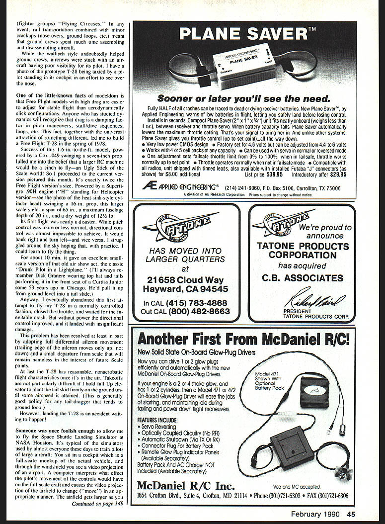
On large-scale biplanes it's worth planning assembly/disassembly procedures and equipment access thoroughly before construction. Making components removable (wings, control surfaces, tail, landing gear, etc.) simplifies finishing, maintenance, repairs, and transport.
Wing and bracing design
- Wings: four separate panels that plug into the fuselage and are supported by functional brace cables.
- Cable materials:
- Primary lift and landing cables: black-nickel-coated stranded steel, ~0.035 in. OD (standard fishing leader).
- Noncritical bracing: similar-diameter nylon monofilament, dyed black.
- Cable end loop technique: pass cable twice through a short length of slightly flattened 5/32" OD aluminum tubing, then squeeze flat and add a drop of cyanoacrylate (CYA) adhesive.
- Turnbuckles: functional turnbuckles (I use DuoPro) are installed at the ends of flying and landing cables for scale appearance and accurate adjustment, but remain fixed length during normal assembly.
Interplane struts and bayonet fittings
- Struts: 1/4-in. thin-walled K&S aluminum tubing with ends flattened to leave an internal ~1/16" gap; faired with balsa to shape.
- Bayonet fittings: cut from 3/32-in. aluminum angle (1/32" thick). Strut ends fit over fittings without positive attachment; brace-cable tension holds them.
- Assembly sequence (summary):
- Plug lower wings into fuselage and attach to landing cables with #4 screws left mostly external so wings droop slightly.
- Fit interplane struts onto lower wings.
- Plug upper wing bayonet fittings into interplane struts.
- Plug upper wings into the fuselage and attach bayonet fittings with two #4 screws each.
- Fully tighten landing-cable screws to tension lift and landing cables and set dihedral.
- Attach monofilament braces between bayonet hooks.
- Although 12 screws are installed during assembly, socket-head screws make the operation fast—only a few minutes.
Washout and flight-safety
- A small amount of washout (trailing edge near the tip warped up) is extremely valuable on Scale models. It helps prevent snap rolls when slowing on approach or pulling off the ground without sufficient airspeed.
- Numerous snap-roll accidents I’ve seen could have been avoided by a couple degrees of washout. Modelers often obsess over CG and neglect wing twist.
Center of gravity, equipment location, and removable firewall unit
- Scale models often tend to be tail-heavy. Solutions include light tails and fat fuselage structure or forward-mounted radio equipment.
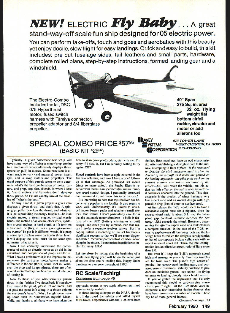
- On the T-28, a removable firewall-and-engine unit is used:
- A thin aluminum plate bolted to the firewall carries the engine, engine mount, and front landing gear; this assembly can be removed as a unit.
- Radio and battery gear are mounted on the forward portion of the main gear box so they remain with the fuselage when the front end is removed.
- Fuel tank sits on top of the equipment box for easy servicing.
- Servo pushrods operate a gang of five bellcranks (two servos for ailerons, two for elevators, one for rudder). The bellcrank gang is permanently attached to the fuselage.
- Quick-links on servo pushrods allow removal of the engine/firewall/equipment assembly while controls remain connected to the bellcrank gang. Access to quick-links is through the cockpit.
- Removing the assembly takes 10–15 minutes and gives excellent access to equipment while leaving wings attached.
Landing Gear Design
- General scheme: sturdy, light, functional rubber shock cords, easily repairable; used successfully on many WW I-models.
- Components and construction:
- Struts: 7/16-in. diameter aluminum tubing, .035 wall thickness, flattened to an oval by clamping between wood blocks. Ends flattened further to leave a gap for mounting.
- Upper end: short 1/8-in. sheet-aluminum spacer fills the gap; drilled for a 6-32 machine screw that mounts to the fuselage.
- Bottom end: slips over a 1/2-in. sheet-aluminum crotch fitting; assembly held by tension in cable braces (no fixed attachments).
- Axle: thin-wall stainless-steel tubing from auto radio antenna (3/32" dia).
- Spreader bars: 1/8-in. dia. steel tubing used for auto hydraulic brake lines; slip over plastic-tubing-covered ends of 4-40 machine screws protruding inside the crotch.
- Axle retention: several #42 rubber bands wrapped around the lower crotch tongue.
- Wheel assembly (outboard from crotch): slider that fits over axle to protect rubber shock cords, short length of rubber tube (auto heater hose) CA'd to slider, brass and nylon washers on each side of wheel, cotter pin to retain wheel.
- By changing materials and sizes, the scheme scales up or down and works on small Free Flight types with thin-wall tubing and monofilament brake wires.
Engine Cooling, Baffles, and Fueling
- Baffling with pressure cowl is standard full-scale practice and desirable on Scale models: maintain pressure by making the air-exit area smaller than the intake; force high-speed flow around the cylinder by making the baffle clearance around the cylinder the minimum area.
- T-28 implementation: a homemade box muffler forms the left-hand side of the baffle and additional .016 aluminum sheet pieces attach to the firewall to form a baffle that forces cooling air about the Super Tigre .90 cylinder.
- Fuel system: a Perry regulator pump is recommended. Benefits:
- Allows engine starting without choking.
- Lets the fuel tank be placed in a remote location.
- Caution: with direct-injection pumps, if the engine floods you must pinch the fuel line to clear it. Setting the regulator to low pressure and cranking until it fires avoids flooding.
Electronics and Speed Controls
- A follow-up on speed controls: the Futaba electric receiver with built-in speed controls I examined uses a frame-rate speed-control design. It has become popular locally and seems to work well.
- Limitations:
- Limited to seven-cell motor battery packs and relatively small motors.
- Built-in BEC automatic motor cutout can be surprising; for that reason I prefer a separate receiver battery.
- The integrated receiver/speed-control approach simplifies installations. Wider market success may yield larger receiver/speed-control combos.
Thrust testing note
- A common test setup uses an electric motor and prop to measure thrust in ounces while varying rpm, power input, motors, and propellers. Remember: a prop at a given rpm produces a given thrust regardless of what turns it. Different motor/battery combinations can be used to achieve the same rpm and thrust, but the spinning propeller is what produces the thrust.
Suppliers and further information
- Aircraft Spruce and Specialty Co., 601 W. Truesdell Ave., Fullerton, CA 92632 — good mail-order source for materials useful to large Scale models (cold-set epoxies, urethane foams, dopes, thinners, various fibers and metals).
- Additional DFW T-28 information:
- Air International (March 1978) — description of the aircraft.
- Photos: Rare Birds (Monty and Pat Groves), 7911 Nissually Dr., Sunnyvale, CA 94087.
Closing
Happy quiet landings to everyone throughout 1990!
Transcribed from original scans by AI. Minor OCR errors may remain.

