
RADIO CONTROL SCALE
Jeff Troy 200 S. Spring Street, Ambler, PA 19002
It's Sunday, January ninth, and it's been an interesting weekend here in eastern Pennsylvania, to say the least. Instead of the usual aggravating snowstorms, we've been plagued with a treacherous ice buildup that has caused all kinds of injuries and immobilized a good portion of the area.
At my home, my eighteen-year-old kit car is in the middle of a full restoration, our other two automobiles are iced in, and the electricity has just been restored after being out of service for much of the weekend. What's more, my entire family has some variety of intergalactic Meeb Zorp flu.
Am I complaining? Nah, but I feel much better about what I've written now that I know that you know today isn't really one of those springy, cheerful, bright-and-sunny May kind of days! All that aside, I'll get to the business/pleasure at hand: scale radio control airplanes.
Docu-Search
We have an AMA member in Poland who is in dire need of a plan for the Piper PA-25 Pawnee. Piotr Zawada — Osiedle Przyjazni 22 m. 141, 61-680 Poznan, Poland — could use a little U.S.-style assistance.
The Pawnee is a reasonably common aircraft, and certainly one of the more popular crop dusters. I'm almost certain that I've seen a kit for this model, but I can't remember where or when. I also seem to remember seeing two or three outstanding Pawnees on the static tables at a WRAM show about three or four years ago. Somebody must have something for Piotr if they dig deeply enough.
If you can help, write a letter or drop a postcard to the address at the top of the column and let me know what you have; I'll do my best to help. If you send a stamped, self-addressed envelope with your request, I'll let you know which Model Aviation issue will contain your Docu-Search item.
Modelers' Projects
Charles L. Neely edits an interesting newsletter for fans of the North American P-51 Mustang: the Mustang Modeller and Enthusiast. Its October 1993 premiere issue is crammed with information that is sure to keep the fires burning in every pony-lover's eyes. The newsletter will be published quarterly; subscriptions are available. For pricing and additional information, write to Charles L. Neely at 4142 W. Cambridge Avenue, Visalia, CA 93277.
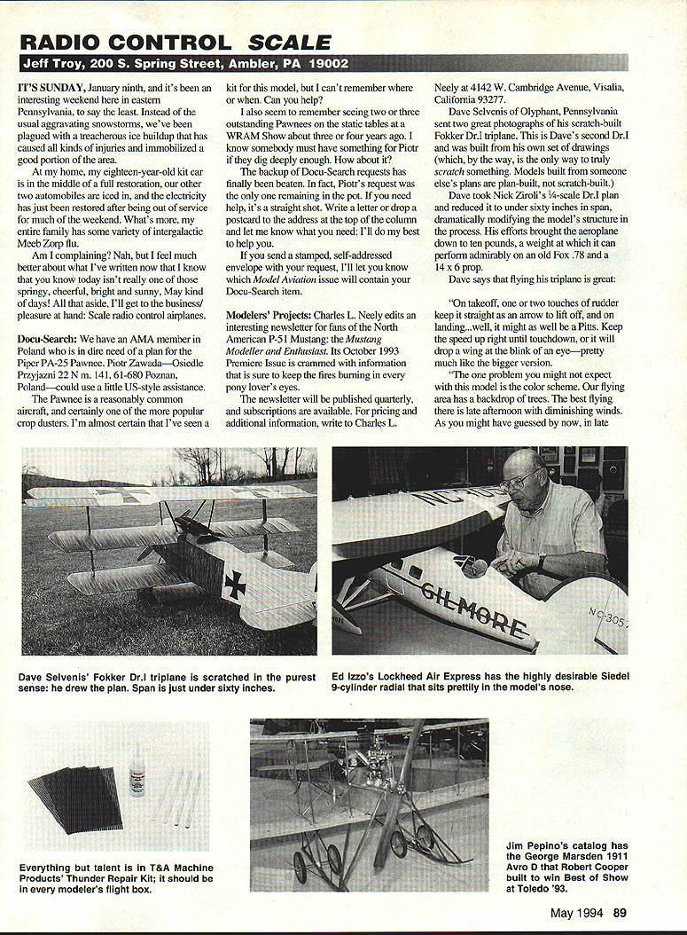
Dave Selvenis of Olyphant, Pennsylvania, sent two great photographs of his scratch-built Fokker Dr.I triplane. This is Dave's second Dr.I and was built from his own set of drawings (which, by the way, is the only way to truly scratch something). Models built from someone else's plans are plan-built, not scratch-built.
Dave took Nick Zirolis's 3/4-scale Dr.I plan and reduced it to under sixty inches in span, dramatically modifying the model's structure in the process. His efforts brought the aeroplane down ten pounds, at which it can perform admirably on an old Fox .78 and a 14x6 prop.
Dave says that flying his triplane is great: "On takeoff, one or two touches of rudder keep it straight as an arrow to lift off, and on landing, well, it might as well be a Pitts. Keep the speed up right until touchdown, or it will drop a wing at the blink of an eye—pretty much like a bigger version."
One problem you might not expect with this model is the color scheme. Our flying area has a backdrop of trees. The best flying here is late afternoon with diminishing winds. As you might have guessed, in late-afternoon sunlight the Fokker just about disappears on landing approach. Maybe next year Dave will paint it a brighter color. Camouflage works. Unfortunately, sometimes it works too well.
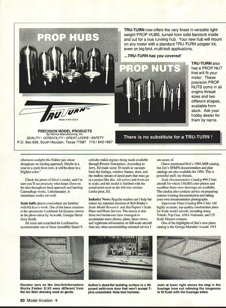
Scale buffs almost everywhere are familiar with Ed Izzo's work. His latest creation is a spectacular Lockheed Air Express, shown in a photo taken in Acworth, Georgia by a friend, Jerry Smith. Ed sized his scratched Lockheed to accommodate the incredible Siedel 9-cylinder radial engines being made available through Proctor Enterprises. According to Jerry, Ed made some thirty molds to vacuum-form fairings, window frames, doors and an endless stream of detail. All screws and rivets are to scale, and the model is finished with the actual paint used on the full-size version. Looks great, Ed.
Industry News
Regular readers can't help but notice my repeated mention of Bob Banka's Scale Model Research and Jim Pepino's Scale Plans and Photo Service. The reason is that these two businesses have managed to accumulate more photos, plans, three-views, and legitimate information on full-scale aircraft than any other aeromodeling-oriented service I am aware of.
I have mentioned Bob's 1994 SMR catalog, but Jim's SP&S documentation and plans catalog are also available for 1994. This is powerful stuff.
- Scale Documentation Catalog #94-2 lists aircraft for which 130,000 color photos and excellent three-view drawings are available. The catalog also contains advice on preparing contest-winning documentation and taking your own documentation photographs.
- Superscale Plans Catalog #94-3 lists 160 highly accurate, top-quality construction plans for scale model aircraft, including many Toledo, Top Gun, AMA Nationals, and US Scale Masters winners.
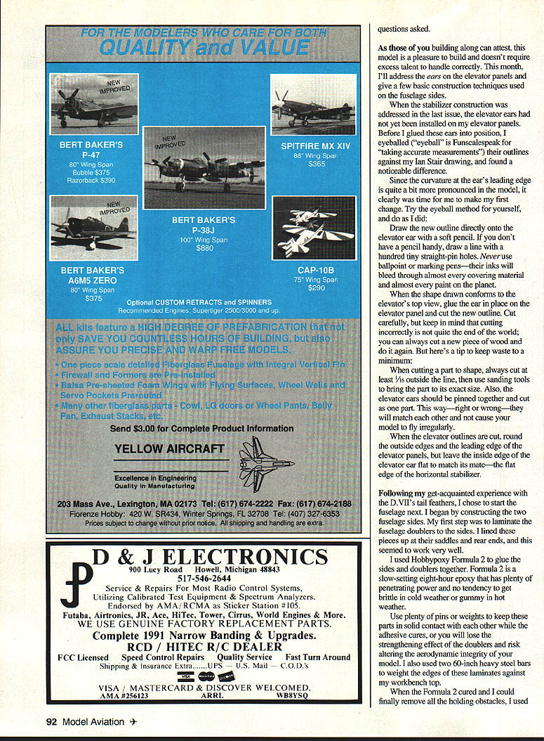
One highlight of Jim's new plans catalog is the George Marsden 1/4-scale 1911 Avro D. Robert Cooper built — winner Best Show Toledo '93. The plan for this model is spectacular and covers every aspect of construction. If you're a sucker for artsy and fragile wooden landing gear, draggy flying wires and functional rigging wires, hand-polished brass hardware, wood stain, and buttonhole fabric, you've just got to have this.
For additional information and catalog prices, contact Scale Plans and Photo Services at 3209 Madison Avenue, Greensboro, NC 27403.
Talk among knowledgeable scale aeromodellers is that Doss Steed has one of the finest plan and pattern sets available for modelers wishing to tackle a 1/4-scale P-51. The documents provided are very thorough and enable any reasonably talented modeler to produce a first-class model more than capable of bringing home the gold. The following quote is found on drawing #1 of Mr. Steed's documentation package, intended for submission to contest judges:
"These drawings were made using North American film series, dated 1944, 24 reels, USAF CAN #278 to 280. The index contains 155 pages which describe all parts (springs, nuts, bolts, and screws)."
Steed's Stuff offers much more than just the six-sheet plan set and a great documentation package. There is also an aluminum spinner, a cast front carburetor air scoop, fiberglass lower front cowling, and a fiberglass air scoop. For additional options you can buy a complete landing gear and tail wheel assembly, inside covers for the gear doors, exhaust stacks, gun ports, a scale four-bladed prop, or even a whole fiberglass fuselage. Three separate photo packs are available, each containing 20 pictures of the full-scale P-51.
Anyone interested in adding what is probably the ultimate 1/4-scale model Mustang should send a stamped, self-addressed envelope and an information request to Steed's Stuff at Route 1, Box 1360, Hartwell, GA 30643.
Are you looking for a good source for bulk miniature fasteners? Jerry Nelson's Nelson Aircraft Company has nickel and black-oxide Phillips sheet-metal screws and steel machine screws, small-head nickel-steel nuts in bags of 50 pieces each, and subminiature steel stop nuts in 25-piece bags. These are available at very reasonable prices and can come in quite handy for long lists of scale applications.
Which would you rather do with your next scale project's canopy: attach it with a piece of dopey-looking striping tape, or hold the canopy frame in place with properly spaced, correctly sized Phillips-head screws? You decide, but try to remember that model also means replicate. How would you grade a model with a taped-on windshield? Send one stamped, self-addressed envelope to Nelson Aircraft Company at 21550 NW Nicholai Court, Unit D, Hillsboro, OR 97124.
They're not just the radio guys. Ace R/C has also become well-known in scale circles since they added a giant Taylorcraft, a Weeks Special, and three Extra 230s to their kit line.
They have now added an appealing group of tiny and refreshing fun-level models to attract those of us with more modest budgets, or just plain simpler tastes. Ace's new Simple Series includes:
- P-51 (WWII fighter) — 35-inch span; designed for .049 to .051 engines; landing gear equipped.
- Me 109 (WWII fighter) — 35-inch span; designed for .049 to .051 engines; landing gear equipped.
- Cap 21 (contemporary aerobatic) — 35-inch span; foam wing construction; no landing gear.
- Extra 230 (contemporary aerobatic) — 35-inch span; foam wing construction; no landing gear.
- Beech Staggerwing — 35-inch span; designed for .09-.15 glow power; not landing-gear equipped.
All five Simple Series "budget busters" are designed with fun in mind: low time commitment, an even lower cash outlay, but maximum enjoyment. The models feature balsa and Lite Ply construction, foam wings, and CAD-drawn plans. Information and pricing is available from Ace R/C at 116 W. 19th St., P.O. Box 472, R/C Dept. #11, Higginsville, MO 64037-0472. Incidentally, Ace also has a great lithograph print available to Staggerwing fans — ask about it when you check for information on the Simple Series Staggerwing kit.
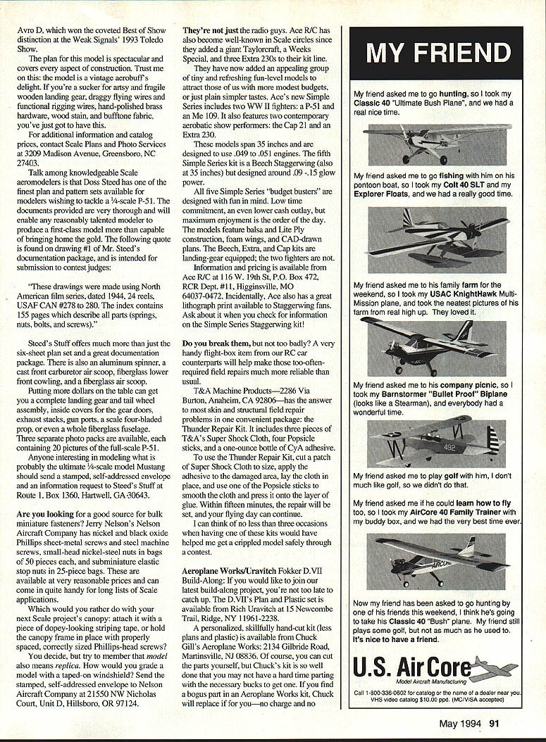
Do you break them, but not too badly? A very handy flight-box item from our R/C car counterparts will help make those too-often-required field repairs much more reliable than usual. T&A Machine Products — 2286 Via Burton, Anaheim, CA 92806 — has the answer to most skin and structural field-repair problems in one convenient package: the Thunder Repair Kit. It includes three pieces of T&A's Super Shock Cloth, four Popsicle sticks, and a one-ounce bottle of CVA adhesive.
To use the Thunder Repair Kit, cut a patch of Super Shock Cloth to size, apply the adhesive to the damaged area, lay the cloth in place, and use one of the Popsicle sticks to smooth the patch and press it onto the layer of glue. Within fifteen minutes, the repair will be set, and your flying day can continue.
I can think of no less than three occasions when having one of these kits would have helped me get a crippled model safely through a contest.
Aeroplane Works / Urvazitch Fokker D.VII Build-Along
If you would like to join our latest build-along project, you're not too late to catch up. The D.VII's plan-and-plastic set is available from Rich Urvazitch at 15 Newcombe Trail, Ridge, NY 11961-2238.
A personalized, skillfully hand-cut kit (less plans and plastic) is available from Chuck Gill's Aeroplane Works: 2134 Gilbride Road, Martinsville, NJ 08836. Of course, you can cut the parts yourself, but Chuck's kit is so well done that you may not have a hard time parting with the necessary bucks to get one. If you find parts missing in an Aeroplane Works kit, Chuck will replace them for you—no charge and no questions asked.
As those of you building along can attest, this model is a pleasure to build and doesn't require excess talent to handle correctly. This month I'll address the elevator ears and give a few basic construction techniques used on the fuselage sides.
When the stabilizer construction was addressed in the last issue, the elevator ears had not yet been installed on my elevator panels. Before I glued these ears into position, I eyeballed ("eyeball" is Funscale speak for "taking accurate measurements") their outlines against my Ian Stair drawing, and found a noticeable difference.
Since the curvature at the ear's leading edge is quite a bit more pronounced in the model, it was time for me to make the first change. Try the eyeball method for yourself, and do as I did:
- Draw the new outline directly onto the elevator ear with a soft pencil. If you don't have a pencil handy, draw a line with a hundred tiny straight-pin holes. Never use ballpoint or marking pens—their inks will bleed through almost every covering material and almost every paint on the planet.
- When the shape drawn conforms to the elevator's top view, glue the ear in place on the elevator panel and cut the new outline. Cut carefully, but keep in mind that cutting incorrectly is not the end of the world; you can always cut a new piece of wood and do it again.
- When cutting a part to shape, always cut at least 1/16" outside the line, then use sanding tools to bring the part to its exact size. Also, the elevator ears should be pinned together and cut as one piece so they match each other and do not cause the model to fly irregularly.
- When the elevator outlines are cut, round the outside edges and the leading edge of the elevator panels, but leave the inside edge of the elevator ear flat to match the flat edge of the horizontal stabilizer.
Following my get-acquainted experience with the D.VII's tail feathers, I chose to start the fuselage next. I began by constructing the two fuselage sides. My first step was to laminate the fuselage doublers to the sides. I lined these pieces up at their saddles and rear ends, and this seemed to work very well.
I used Hobbypoxy Formula 2 to glue the sides and doublers together. Formula 2 is a slow-setting eight-hour epoxy that has plenty of penetrating power and no tendency to get brittle in cold weather or gummy in hot weather.
Use plenty of pins or weights to keep these parts in solid contact with each other while the adhesive cures, or you will lose the strengthening effect of the doublers and risk altering the aerodynamic integrity of your model. I also used two 60-lb heavy steel bars to weight the edges of the laminates against my workbench top.
When the Formula 2 cured and I could finally remove all the holding obstacles, I used Zap-A-Gap CA to quickly glue the lower fuselage stringers in place ahead of the wing saddles.
The next step called for construction of the rear fuselage sides, which are outlined with 3/8-inch square balsa sticks that rest on the ledges created by the lamination of the sides and their doublers.
I could find no reference for bridging the 1/8-inch gaps that would result in the side of the model because of this. The top and bottom fuselage longerons would be level with the doublers, but would end up sitting 1/8 inch behind the sides of the fuselage.
Two options were open to me:
- I could take the easy way and cut 1/8 inch away from each longeron before gluing them in place. This would cause them to lay flat against the plan with the fuselage sides and still provide a firm gluing base along the sides and doublers. The drawback is that my 3/8-inch pieces would then only be 1/4-inch pieces where they contacted the side components, and the steps in the wood that resulted from my cuts would surely become weak points.
- I could proceed with construction as instructed and apply my solution to the problem after each side was completed. I chose this course.
I dropped a few 1/8-inch shims around the fuselage outline to block up the rear longerons to the same height as the side panel they would rest upon, then I proceeded to cut, fit, sand, and Zap-A-Gap the longerons and uprights into position.
The first basic side was finished with the addition of the four 3/8 x 1/4 cross braces in the four rear fuselage bays. When the CA had cured, I lifted this first side from the plan, removed the waxed-paper backing, turned it over, and laid it flat on the workbench.
I covered this side with waxed paper and used 1/4-inch shims to replace the 1/8-inch shims originally used, then I proceeded to build the second side directly over the first. This duplication method eliminates almost every chance for error while keeping both sides uniform.
When my Fokker's left and right sides were completed, I still had to deal with those annoying 1/8-inch steps. My fix was rudimentary: I cut four 3/16-inch wide strips of 1/8-inch soft balsa—each 14 inches long—and Zapped them in place against the steps and over the longerons.
When the CA cured, I planed and sanded these balsa longeron doublers to blend smoothly from the sides into the 3/8-inch square rear fuselage sticks. The whole correction took about fifteen minutes and will completely eliminate any buckle in covering that would have been caused by that unsightly step from the rear to the forward sides.
When the fuselage curves to join at the rear, any evidence of these balsa fillets will vanish. The sides were finished by pinning them together and using 100 Ruff-Stuff on the Tex-Bar to sand their outlines flush.
I finished my hull-building session by assembling one of the two laminated fuselage bulkheads directly over the plan—covered by waxed paper, of course. Then I snapped a few more photographs, vacuumed the bench, put my T-pins back in their plastic container, capped my glue, and said goodnight.
Goodnight, build straight, and fly safely. I'll talk with you again.
Transcribed from original scans by AI. Minor OCR errors may remain.

