
Introduction
As is always the case, if anyone has a comment or question about the USC (or about anything else), write and I'll do my best to answer all.
Hobby Project Panel Labels
Labels such as those in the USC and in other articles (for example, the Pulse Mini-Lab and the Servo Cycler) add considerable appeal to homemade instruments and frequently prompt reader inquiries. Since so many have asked, here's how I do it.
Layout and drawing
- At the outset of a project I sketch a rough panel layout — an initial arrangement of switches, knobs, connectors, etc.
- I follow that with a dimensioned layout on my computer. I use TurboCAD by IMSI for panel layouts, PC-board assembly drawings, schematics, and model-construction plans.
- I usually draw and print panel layouts full-size and print two versions for each panel.
Printing and applying the construction template
- Print a "construction" version showing all drill centers.
- Attach the paper pattern to the metal panel (usually aluminum) with a smooth layer of Elmer's Glue Stick.
- Position the paper pattern and press it in place.
- Center-punch the hole locations and drill.
- Soak the panel and paper in warm, soapy water to dissolve the Elmer's; rinse and dry.
- Deburr the holes.
Final paper label and finishing
- Print the second (final) paper label on higher-quality paper and use the "best" print option on an ink-jet printer.
- Remove mechanical marks (drill centers) and add appropriate lettering using the program's layer feature.
- Cut a few hole locations in the paper with a fresh X-Acto™ #11 blade and use those holes to align the paper with the drilled panel holes.
- Attach the final paper label with the Elmer's Glue Stick, smoothing with a cloth over the paper while pressing.
- Cover the printed label with clear Contact® paper for protection. I sometimes make the paper label slightly undersize so the clear cover overlaps the metal by roughly 1/16 inch.
- Finally, cut out the remaining label holes with an X-Acto™ at the drilled hole locations.
TurboCAD note
Visit turbocad.com and download the free version to try; it is a fully workable but smaller version of the product. It worked well enough that a friend opened my original SSC drawing files with the demo version and later purchased the full software. TurboCAD is economical, powerful, and supports file transfer with AutoCAD®.
Wingo (Hobby Lobby ARF) Repair
The Wingo is an incredibly popular Almost Ready-to-Fly (ARF) electric model. Mostly foam construction notwithstanding, it is a robust airplane. A local modeler landed a bit fast on a small stone, which punched a hole approximately 1" by 2" in the bottom front of the fuselage pod. Here’s the repair I used.
Repair method
- Soak a wad of cotton with Titebond yellow (carpenter's) glue — not too much glue, but soaked all the way through the cotton.
- Stuff the cotton/glue glob into the jagged foam opening, work and smooth it so it fills the void and blends into the perimeter.
- Let dry — the drying took two full days for me.
- For added durability, coat the repaired area with five-minute epoxy (the bottom front is likely to hit the ground in nose-down landings).
Result: the cotton/glue combo formed a tough patch as durable as the foam. For a faster cure next time, thin the yellow glue a bit with water and use a heat lamp to speed drying.
Pushrod Adjustment for Small Airplanes
Adjustable clevises are rarely used on small airplanes, making pushrod adjustment a challenge. The "Z-bend" approach can be difficult for fine adjustments. My solution:
- Make the pushrod in two pieces and couple them roughly in the middle with a 1/16-inch wheel collar.
- Use steel wires thin enough to fit into the collar bore and allow the rods to overlap about 3/4 inch.
- Adjust overlap for correct overall length, then tighten the collar set screw.
- For heavier pushrods, use a larger set screw or a 1/8-inch collar.
Carpet Runway
I made a carpet runway for indoor flying at a local mall: 6 feet by 24 feet, suitable for small electrics or small glow models.
- If you plan to use such a facility, check with mall management about liability insurance and rules for flying indoors.
- Most important: have fun and meet other fliers.
Reader Contributions
I'm always interested in hearing about your repair methods and shop tips. Send them to me at the magazine address.
Holidays / Christmas Shopping and Building Habits
Everyone should receive this magazine near the end of November, so there's still time to check catalogs for books, parts, or perhaps an engine you've put off buying for a new scale model. It can help to leave a list or a catalog with certain areas highlighted — it usually works.
Have you started your new scale model for the next flying season? If you can fly year-round where you live, great. One habit I’ve adopted is to do something on my current project each day. This keeps focus on the project at hand instead of starting another model while one remains unfinished. (You don't start two or three models at the same time, do you?)
Kent Walters’ Douglas SBD Dauntless
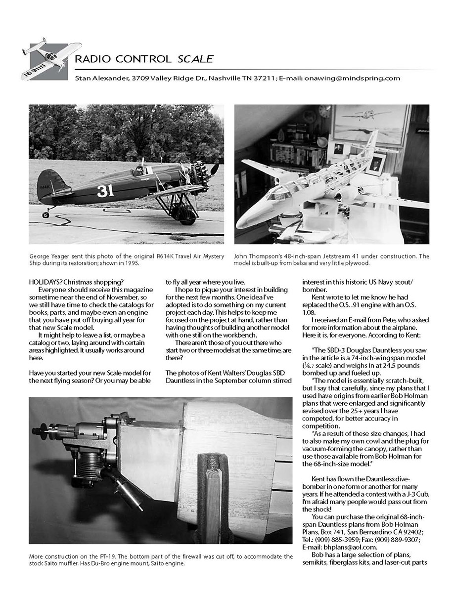
The photos of Kent Walters' Douglas SBD Dauntless in the September column stirred interest. Kent wrote to say he replaced the O.S. .91 engine with an O.S. 1.08. In response to a reader's request for more information, Kent supplied these details:
- The SBD-3 Douglas Dauntless in the article is a 74-inch wingspan model (1/6.7 scale) and weighs 24.5 pounds bombed up and fueled up.
- The model is essentially scratch-built, but the plans used have origins in earlier Bob Holman plans that Kent enlarged and significantly revised over more than 25 years to improve accuracy for competition.
- Because of the size changes, Kent had to make his own cowl and the plug for vacuum-forming the canopy rather than use those available from Bob Holman for the 68-inch model.
Kent has flown the Dauntless in one form or another for many years.
Bob Holman Plans contact:
- Bob Holman Plans, Box 741, San Bernardino, CA 92402
- Tel.: (909) 885-3959
- Fax: (909) 889-9307
- E-mail: bhplans@aol.com
Bob carries a large selection of plans, semikits, fiberglass kits, and laser-cut parts for many designs. If you’re serious about scale modeling, consider having his catalogs on hand.
Top Gun Invitational Update
Top Gun will be back at the West Palm Beach Polo Club (FL) this spring. There are new safety rules for jets this year that should be published by the time this column appears. The flightline will again be canted to keep the microwave tower out of harm’s way.
- Dates: April 25–29
- For special rates on rooms and travel: Cindy Burkley, Southport Travel, (800) 735-0401 or (800) 752-5615
- For contest information: Frank Tiano Enterprises, (561) 795-6600
Don Smith Scale Plans
I received a set of Don Smith's Fw 190A-8 plans, a possible subject for modelers who like Fw 190s. The A-8 was a later model with a longer nose than the earlier A-0 to A-4 versions, and it was built before the inline-powered D ("Dora") versions.
Model dimensions from the plans:
- Wingspan: 89.6 inches
- Length: 76.4 inches
- Wing area: 1,405 square inches
If you're interested in building an Fw 190A-8, these plans could be a good starting point.
Transcribed from original scans by AI. Minor OCR errors may remain.

