
RADIO CONTROL: SCALE
Jeff Troy 19 East Mt. Pleasant Avenue, Ambler PA 19002
IN JANUARY, Southern California hosted two major hobby expositions: the International Modelers Show (IMS) in Pasadena, and the Endless Horizons Expo in Long Beach. It was fun for me to attend those shows as a member of the press and not as an exhibitor locked into a booth, as I had always been. I saw these shows as the consumer saw them.
Endless Horizons had a full-line mix of exhibitors; there were airplane, car, boat, train, and plastics manufacturers of every size and description. IMS was more of an airplane modeler’s show, although there was a solid cross-section of hobbies.
The weather was fantastic, and the Southern California hospitality and dining were first-rate (thanks, Barbara, Roy, and Susan). The only negative aspect was that both shows took place during the same four days, which put a terrific burden on exhibitors and consumers. I spent two days at each event, but that’s not convenient for exhibitors, who must either choose to attend one show or bear the costs of participation in both.
I’ll keep my text on the short side and give you a chance to see some of the highlight photos.
Spitfire Build-Along
I actually got this project started! This installment won’t be big, but it will be enough so that you know the model is officially on the bench and in progress.
My favorite choice for a building surface has long been the solid-core door. Some builders will shout the virtues of cardboard, cork, or ceiling tiles, but they all give slightly when pressure is applied, causing the possibility of misaligned parts. Hollow-core doors are not bad, but their surfaces tend to give slightly between internal crossmembers.
If you prefer something other than a solid-core door, go ahead and use it, but to me the extra cost of a solid-core door does not matter when my modeling enjoyment may be at stake. Get a door—just don’t get a warped one.
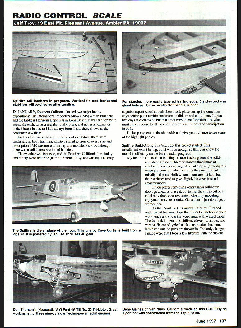
As the Dynaflite kit’s manual instructs, I started with the tail feathers. Tape the plan’s tail section to your workbench and cover the work areas with waxed paper. The 3/16"‑thick horizontal stabilizer, elevators, rudder, and vertical fin are of typical stick construction, but some laminated outline parts are thrown in. The only changes I made were that I took a few liberties with the die-cut parts.
For a sturdier, more easily tapered trailing edge, 1/32" plywood was glued between balsa on the elevator panels and rudder. The rudder and elevator trailing edges are constructed of three die-cut balsa pieces laminated and glued atop one another to yield 3/16" thickness. Since I will be tapering the rudder and elevator panels, I omitted the center laminate part and replaced it with 1/32" plywood. The result is a strong trailing edge; the plywood centerline holds its shape during sanding and also provides a visual sanding guide during tapering. It gives better ding resistance when the model is completed.
Creating the trailing edges:
- Of the three die-cut trailing edge parts the kit provides for the rudder, discard the least desirable one.
- Using medium cyanoacrylate (CyA) glue, glue the rudder trailing edges to a 6 x 12 sheet of 1/32" plywood (available at your nearest hobby shop).
- After the glue has set, use an X‑Acto knife with a new #11 blade to score the plywood around the outline of the balsa trailing edge. Excess plywood should come away cleanly after three or four passes.
- Apply CyA to the plywood side of the assembly and press the second die-cut balsa part in place atop the plywood. You should have a three-piece rudder trailing edge with 1/32" plywood sandwiched between two die-cut balsa parts.
- Repeat the procedure to create the elevator trailing edges. 3/32" thinner-stock assemblies would be fine.
The elevator trailing edges will be slightly thinner than the stock assemblies, so shim them when attaching to the rudder and elevator structures. I used 1/32" plywood scraps under the trailing edges when I glued them in place. Don't worry about a 1/64" off-center; the sanding process will cure any minor asymmetry.
When the outline parts are in place, add the 1/4" x 3/8" ribs. Cut each rib slightly oversize and use a T‑bar to sand them to the exact shape. Remove the pins when the CyA has cured and begin the planing/sanding process.
Before I sand, I use a Fix razor plane to remove excess wood. Be careful to work with the grain of the wood and shave only a small amount with each stroke. When the surfaces are rough-shaped, use #100 paper on the T‑bar to give the parts their final shape.
Use fresh sandpaper with no rough edges to sand the tail parts at a 45° angle to the ribs, preventing most chances of digging into the ribs, leading edges, tips, roots, or trailing edges. Sanding pressure should never be applied to the ribs—just to the outline parts. Use the line of the 1/32" plywood to get a balance on the control surfaces' trailing edges.
Spend extra time block-sanding the horizontal stabilizer and the vertical fin. If you have the energy, try to remove 1/16"–3/8" of the thickness. Sheet one side of the stab and fin with 1/16" light balsa, then turn the parts over and sheet the other sides.
I am using the Squadron/Signal publication Spitfire in Action (#1039) as my documentation source for this casual project, but during the construction phase it might be helpful to have an additional reference. I obtained a 1/2‑scale Airfix Spitfire VB kit (#02046) from the local hobby shop; along with the Squadron book, it should help answer my most basic questions while I work.
I'll get the fuselage underway in the next installment.
Docu-Search
Just when you think something is finished, it pops up and starts things rolling again. For C-124 fans, long-lost friend Don Briggs has made his move, and I have his address. If you'd like to try to locate the 124, write Don at:
- Don Briggs, Box 238, Curtis NE 69025. He has much information to share, but he insists that you not try to telephone him at home—please limit contacts to the mail.
A postcard was received from K.D. Wilson, who claims to have provided the plan from which Don Briggs's C-124 was built. K.D. has a mint Airsco‑Craft C-124 kit he used to create printwood and duplicates of the plan—these materials are available for those interested in this aircraft. Contact K.D. at:
- K.D. Wilson, 2324 E. Florida St., Evansville IN 47711-4812.
Bart Ramsay is interested in the Handley Page Hampden and would like to construct one for two Quadra 45 engines. He has three-views from Scale Model Research, and there is a full-scale Hampden in his local air museum. He would like to draw the final plan himself but needs a basic plan (in any scale) upon which he can elaborate. Bart has ModelCAD—material in that format can be very useful. Contact Bart at:
- Bart Ramsay, Apartment 1203, 98 Tenth St., New Westminster B.C., CANADA V3M 6L8.
Neil Kube seeks a large-scale kit for the PBY-5 Catalina flying boat. If anyone knows of anything available in a 100‑inch span or more (in addition to the G&P kit), please contact Neil at:
- Neil Kube, 445 Northwood Dr., Guilford CT 06437-1162.
Enjoy the pictures. Until next time, build straight and fly safely. We'll do this again.
Transcribed from original scans by AI. Minor OCR errors may remain.

