
Radio Control: Scale
Bob and Dolly Wischer
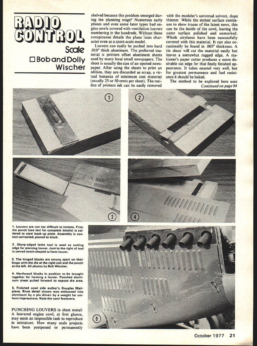
PUNCHING LOUVERS in sheet metal:
A louvered engine cowl, at first glance, may seem an impossible task to reproduce in miniature. How many scale projects have been postponed or permanently shelved because this problem emerged during the planning stage? Numerous early planes and even some later types had engine cowls covered with ventilation louvers numbering in the hundreds. Without these conspicuous details the plane loses character even as a sport-scale model.
Louvers can easily be punched into hard .010" thick aluminum. The preferred material is printers' offset aluminum sheets used by many local small newspapers. The sheet is usually the size of an opened newspaper. After using the sheets to print an edition, they are discarded as scrap, a virtual bonanza of minimum cost material (usually 25 or 50 cents per sheet). The residue of printers' ink can easily be removed with the modeler's universal solvent, dope thinner. While the etched surface continues to show traces of the latest news, this can be the inside of the cowl, leaving the outer surface polished and unmarked. Whole airplanes have been successfully covered with this material. It can also occasionally be found in .005" thickness. A tin shear will cut the material easily but leaves a somewhat ragged edge. A stationer's paper cutter produces a more desirable cut edge for that finely finished appearance. It takes enamel very well, but for greatest permanence and fuel resistance it should be baked. Materials that are easily obtainable and likely to be found in most modeler's workshops. Requirements are two hardwood blocks, a cabinet hinge, a hard piece of metal such as a lathe cutting tool, two scraps of steel, two pins made from short lengths of music wire, and wood screws for the hinge.
In the example shown in the photos, the hardwood blocks were cut from 3/4"-birch 3" wide and 1-1/2" longer than the aluminum cowl length. A slot is cut across the width of one block 1" from its end to fit the lathe tool tightly. This should be a press fit into the block and should be set in flush with the surface when pressed into place. A lathe tool was used because it is extremely hard material which will not wear along its cutting edge. If this tool is not available, any piece of steel such as 3/16"-sq. key stock may be substituted, since it is not likely to wear out during the few operations to be made producing a single louvered cowl.
A notch is cut into the lower wood block adjacent to the steel tool. This notch should be the approximate external shape of the louver to be punched and can be made with an X-acto knife. If louvers are to be cut in sequence, to form a continuous row, a second notch is needed toward the end of the block. This notch can be cut across the full width of the block as shown in the photo. Its spacing from the first notch determines the exact spacing between louvers in a row. If more than one row of louvers is to be cut, a relief notch must also be made along the length of the block to avoid flattening the previous row. This completes the die half of our tool.
The punch that cuts through the aluminum is filed from a strip of steel to the exact shape of the louver. The punch is then sweat soldered to a 1/16"-thick steel back-up plate. This assembly will be cemented and pinned to the upper block in later steps.
The two blocks are now hinged together at the end opposite the notches. When drilling the screw holes for the hinge, the blocks should be spaced apart the same amount as the thickness of the back-up plate. The punch is now laid into the notch loosely while the hinged blocks are brought together for alignment. Mark the approximate location of the back-up plate on the upper block and spread a strong contact cement such as Walther's Goo on the back-up plate and the marked off area of the wood. Allow ten minutes for the cement to dry. With the punch set in position in its notch, bring the blocks together.
When the cemented areas make contact as the tool is closed, perfect alignment should result between punch and die. Dowel the back-up plate to the upper block with short lengths of 3/32"-dia. music wire to prevent possible shifting.
Test the operation on a scrap of aluminum. A sharp blow with fist or hammer will drive the punch through the aluminum, forming a louver. If there is evidence of tearing or notching along the cut edge it usually indicates too much clearance between punch and die. This clearance is easily adjustable by means of paper shims inserted between lower hinge leaf and block. In the case of stubbing due to interference between punch and die the shims would be inserted on the opposite side of the hinge. Shims will very likely be required because of the low quality fit in the pin of a cabinet hinge. A heavy paper about .003" thick provides the most useful incremental changes and fine tuning is possible with thinner paper.
While all of this may sound like a large project, I was able to produce my tool with the help of a table saw in slightly more than one hour. A single cowl side punched with 48 perfectly spaced and uniform louvers was produced in 30 minutes. Alternate methods such as fake glued-on strips would have taken much longer with doubtful quality in the end result. An obvious benefit is that the louvers are functional, as they were in the prototype, and the total area of 150 ventilation slots is sufficient to cool a .60 engine in my Douglas Mailplane.
To properly cool an engine enclosed in a cowl, a baffle arrangement to control and direct the flow of air through the cylinder fins is an absolute necessity. This can be made from aluminum or plywood. The baffle should fit the cylinder closely to force all incoming air to flow past and through the fins. The effect desired is similar to that used in full-size planes, where the opening for entering air is larger than the baffle opening around the engine. This creates a pressure cowl which effectively forces air past the fins at a velocity greater than that of the slipstream. It is desirable for the air outlet behind the engine to have an area larger than the inlet, or at least larger than the baffle bypass area. In the case of a louvered cowl this is the total area of all louvers, keeping in mind that a swarm of small louvers may be somewhat lacking in efficiency as compared with larger and smoother openings.
When thin aluminum is used for a baffle it needs to be braced so that it cannot deflect due to pressure. Deflection will spoil the effectiveness and permit incoming air to find a path of lesser resistance rather than flowing through the fins. When an overcharged engine sagged during a flight, this was found to be the reason. After bracing the baffle there was immediate improvement. Mounting a cowl too close to a firewall causes a damming effect obstructing air flow and can result in overheating.
Bob Wischer, Rt. 1, S-221 Lapham Peak Rd., Delafield, WI 53018.
Transcribed from original scans by AI. Minor OCR errors may remain.

