
Radio Control: Scale
Bob and Dolly Wischer
EXPERIMENTAL Aircraft Association members, for a number of years, have been building planes that are reduced-size versions of military aircraft. Their problems in scaling down are similar to those encountered by modelers. Ben Owen of EAA headquarters staff, who is also an AMA modeler, has summarized the scaling technique as follows:
SCALING AIRPLANES USING A 1-FT-SQ. CUBE AS AN EXAMPLE
Dimension: Standard 3/4 Scale 1/2 Scale 1/4 Scale Linear .......... 1 foot .75 .5 .25 Area, square foot . 1 sq. ft. .562 (9/16) .25 (1/4) .062 (1/16) Volume, cubic foot (or weight) . 1 cu. ft. .422 (27/64) .125 (1/8) .0156 (1/64) Surface Area of Cube, sq. ft. . 6 sq. ft. 3.375 (56.25%) 1.5 (25%) .375 (6.25%)
What this proves, or shows, is that there are different reductions in each measurement in scaling. For convenience, engineers have historically used linear measurement when scaling. The fact that a linear reduction of 1/2 does not mean 1/2 of the area or 1/2 of the weight or volume should be clearly kept in mind. Examples:
Formula 1 Airplane Length 16 ft. .............. 1/4 scale model 4 ft. Wing area 68 sq. ft. ........ 4.125 sq. ft. (594 sq. in.) Weight empty, 500 lbs. ...... 7.81 lbs.
Sabre Jet F-86 Length 37 ft. .............. 1/2 scale airplane 18.5 ft. Wing area 287.9 sq. ft. ..... 71.975 sq. ft. Weight 10,000 lbs. .......... 1250 lbs.
It would appear that scale modeling and home-built aircraft are not too different, which helps to explain the prize-winning potential of custom-built planes that are designed or constructed by modelers, particularly those who may have been scale oriented. A good example is the Steen Skybolt of former scale modeler Hale Wallace who has trophies for both sizes of planes.
Using scale models for stall/spin testing:
Another interesting aspect of scale modeling is the use of radio-controlled planes in design and testing techniques for stall and spin evaluation of general-aviation aircraft. Several years ago a paper on the subject was written by Sanger M. Burk of NASA and Calvin F. Wilson of Piper Aircraft in which they described the development of a relatively inexpensive radio-controlled model stall/spin test method and the operational experiences of NASA and Piper in utilizing the technique.
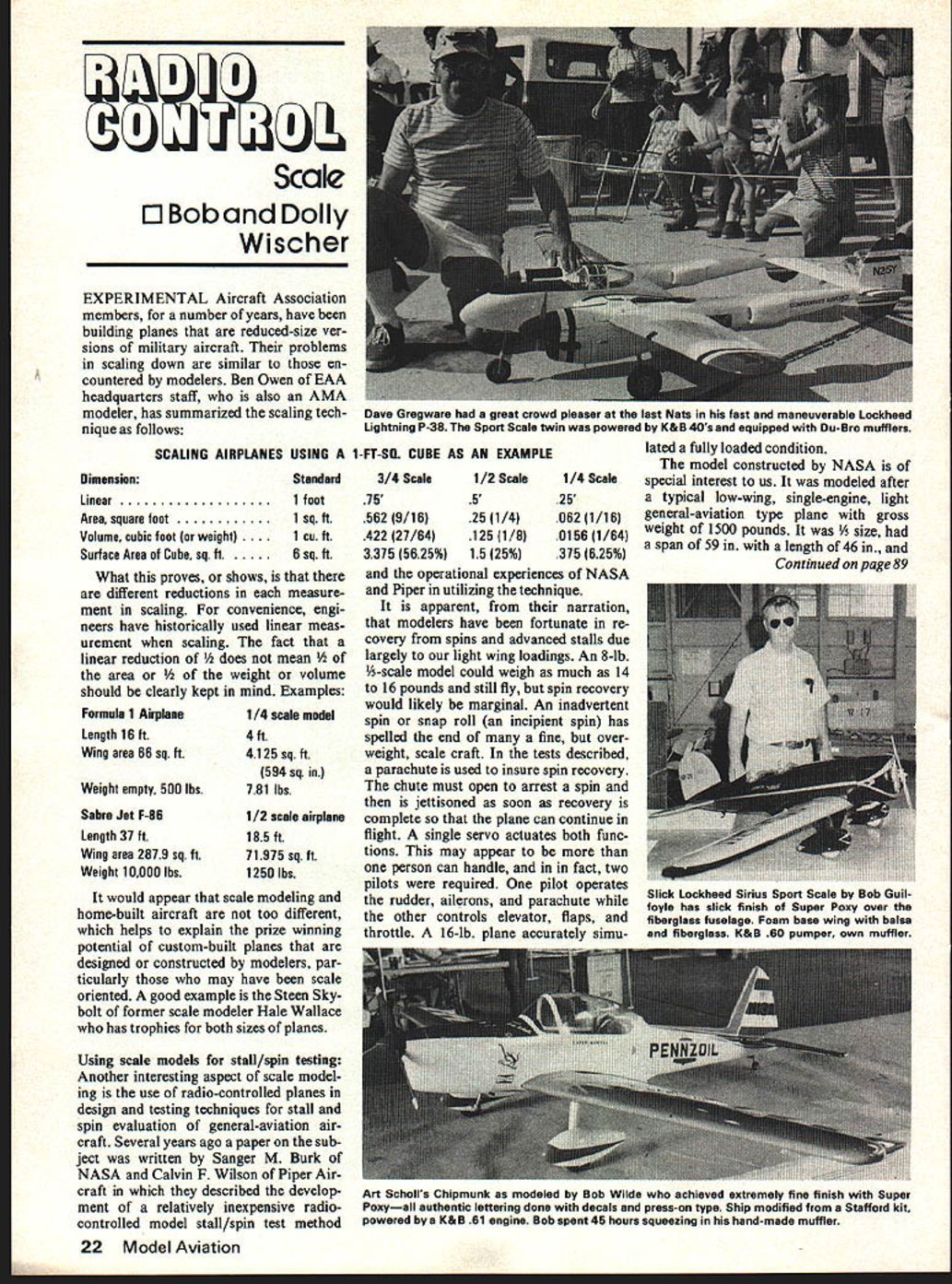
It is apparent, from their narration, that modelers have been fortunate in recovery from spins and advanced stalls due largely to our light wing loadings. An 8-lb., 1/4-scale model could weigh as much as 14 to 16 pounds and still fly, but spin recovery would likely be marginal. An inadvertent spin or snap roll (an incipient spin) has spelled the end of many a fine, but overweight, scale craft. In the tests described, a parachute is used to insure spin recovery. The chute must open to arrest a spin and then is jettisoned as soon as recovery is complete so that the plane can continue in flight. A single servo actuates both functions. This may appear to be more than one person can handle, and in fact, two pilots were required. One pilot operates the rudder, ailerons, and parachute while the other controls elevator, flaps, and throttle. A 16-lb. plane accurately simulated a fully loaded condition.
The model constructed by NASA is of special interest to us. It was modeled after a typical low-wing, single-engine, light general-aviation type plane with gross weight of 1500 pounds. It was 1/5 size, had a span of 59 in. with a length of 46 in., and had freon actuated retracts, very similar to our average scale planes. The plane differed from average in one respect in that the values of moment of inertia about the roll and pitch axis were reduced by special construction techniques. This change is important to us who would like to avoid the unexpected surprise of a spin or low level snap roll. Light and strong construction, especially near the tail and wing tips, is the essential element.
The model had a fuselage of laminates of fiberglass cloth impregnated with resin and had wings of balsa covered with fiberglass. The resin weight is kept to a minimum by squeezing it from the laminates in the molding process, because resin contributes little to strength. Tail surfaces and wing tips are made of balsa and free-foaming plastic for light weight. Ballast was then added to place the center of gravity at the desired location and to bring the weight up to the desired 16 pounds.
The engine in the test model was a standard .61 completely cowled as in many scale planes and had the same problem encountered by most of us in similar situations. It overheated. While our answer to this would be control of airflow through ducts and baffling, the NASA engineers chose a different approach. They added a large heat sink to the engine. This consisted of four large circular aluminum fins attached tightly to the cylinder. Because the spin tests would not permit large center of gravity excursions, the fuel tank was located at the CG and a pressure system with regulator was employed.
One of the interesting aspects of the tests was the telemetry method which returned information to the ground by means of a seven-channel model type transmitter, without case, on board the plane. This relayed signals from seven sensors measuring angle of attack, side slip, and control positions. A hobby receiver on the ground had servos operating potentiometers for recording on an oscillograph.
Another technique, which has been used by modelers and should be used more often, is the practice of utilizing a second plane, similarly loaded, to gain experience before flying a plane that may have taken years to build. Start tests with the practice plane loaded lightly and then add weight until it is as heavy as the finished scale model will be. The pilots used the method to good effect since the landing speed increased greatly during the time weight was being increased. It was found that a runway 1000 feet long and 100 feet wide was required.
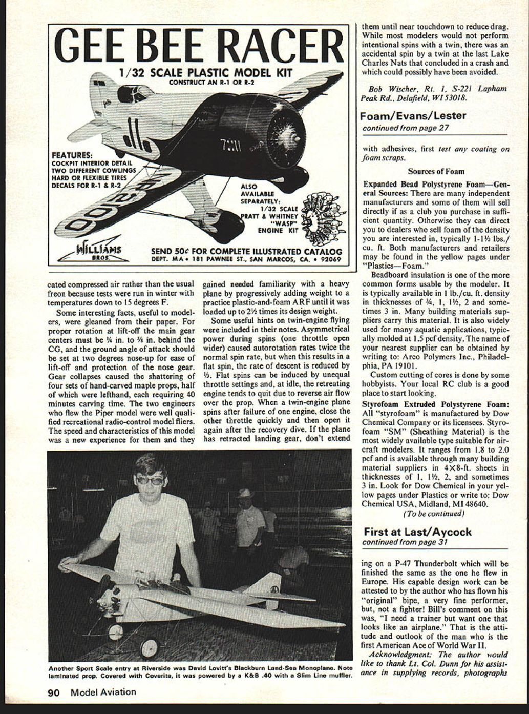
The Piper tests were conducted with a twin .60-powered, 1/4-scale, 15-lb. plane. The righthand Super Tigre engine was modified by rotating the front bearing to give opposite rotation. These tests also employed two pilots and a spin recovery chute. Like the NASA plane it had a fiberglass fuselage with two layers of cloth from nose to wing trailing edge and one layer to the tail. A polyurethane foam wing core was covered with 3/32 in. balsa and finished with fiberglass cloth and epoxy resin. The retract gear was powered by dessi- desiccated compressed air rather than the usual freon because tests were run in winter with temperatures down to 15 degrees F.
Some interesting facts, useful to modelers, were gleaned from their paper. For proper rotation at lift-off the main gear centers must be 1/4 in. to 3/8 in. behind the CG, and the ground angle of attack should be set at two degrees nose-up for ease of lift-off and protection of the nose gear. Gear collapses caused the shattering of four sets of hand-carved maple props, half of which were lefthand, each requiring 40 minutes carving time. The two engineers who flew the Piper model were well qualified recreational radio-control model fliers. The speed and characteristics of this model was a new experience for them and they gained needed familiarity with a heavy plane by progressively adding weight to a practice plastic-and-foam ARF until it was loaded up to 2 1/2 times its design weight.
Some useful hints on twin-engine flying were included in their notes. Asymmetrical power during spins (one throttle open wider) caused autorotation rates twice the normal spin rate, but when this results in a flat spin, the rate of descent is reduced by 1/2. Flat spins can be induced by unequal throttle settings and, at idle, the retreating engine tends to quit due to reverse air flow over the prop. When a twin-engine plane spins after failure of one engine, close the other throttle quickly and then open it again after the recovery dive. If the plane has retracted landing gear, don't extend them until near touchdown to reduce drag. While most modelers would not perform intentional spins with a twin, there was an accidental spin by a twin at the last Lake Charles Nats that concluded in a crash and which could possibly have been avoided.
Bob Wischer, Rt. 1, S-221 Lapham Peak Rd., Delafield, WI 53018.
Transcribed from original scans by AI. Minor OCR errors may remain.

