
Radio Control: Scale
Bob & Dolly Wischer
Control Reversal
The subject of instability was explored in a recent column. We touched on the treacherous situation in which the control stick needed to be pushed, rather than pulled, to regain flying speed and stop the model's descent. Having to do this is a manifestation of the phenomenon called control reversal. Scale models are particularly susceptible because they often have low power relative to their weight.
With throttle open and flying at full speed, if we apply up elevator the nose will rise and the plane will climb. If this process is repeated several times with additional up elevator, we soon reach the point where the nose comes up but there is no climb because there is insufficient power available to maintain speed. If up elevator control is moved further, the nose will again rise but the plane will begin to descend in a mushing condition. At this point we see the effect of control reversal: up elevator has caused the airplane to descend! To recover flying speed and keep the plane in the air we must apply down elevator to regain lift. Even though the wing was not completely stalled, the climb had been reduced to zero and then gone beyond to begin a descent. Passage through this zone is dependent upon the amount of up elevator available. When control-surface movement is great enough the descent can be quite rapid. If the flier becomes alarmed and applies more up elevator, a stall and disaster follow. Gravity and drag from the high angle of attack have combined to cause control reversal.
In a glide with power at idle the same condition can be precipitated with identical results. Knowledge of the phenomenon can be used to advantage. For example, when landing with a dead engine, to stretch the glide use slight down elevator; to shorten the gliding distance, up elevator will cause the mushing rapid descent. This must be used with caution or the model will continue into the ground and be damaged. Up elevator must be relaxed to gain speed before touching down. Try this at altitude first to acquire familiarity. Keep in mind that turbulence and wind friction over the earth's surface will accelerate descent near the ground.
The greatest rate of climb on most scale models is not an extremely nose-high attitude with large angle of attack, but occurs at a modest angle. During the glide it will be found that the same angle of attack and airspeed used in climbing will result in the flattest glide and the longest distance traveled. Lifting the nose with elevator control will steepen the glide after this flattest-glide condition has been established, demonstrating again reversal of controls. What we are really saying is that elevator controls speed and throttle controls altitude. Recognition of these conditions in flight can prevent stalls and spins that can reduce a model to a bundle of sticks. It must be kept in mind that all of the conditions previously described are worsened during even a mild turn. Once a wing has been lowered for a turn, part of the lift is being employed to change direction and is lost against gravity.
Because we are not riding in the model, the exact angle of the nose above the horizon is difficult to ascertain. When we experimented with this phenomenon in our Taylorcraft it became more easily visible. With throttle closed, the control wheel was pulled back very gradually, keeping the nose in the level-flight position. After a minute or two the wheel had reached its rearward stop with up elevator fully applied. The airspeed indicator read 35 mph, near our stalling speed but just above the stall as we felt no buffeting. The Taylorcraft was falling rapidly in a level-flight attitude, like a parachute. If the descent had been continued to the ground it would have been disastrous. To stop the descent, throttle was opened and elevator control relaxed until return to normal flight. The best example to be found in model flying is the parachute-like descent of a de-thermalized free-flight plane.
To avoid control-reversal conditions we must fly at angles of attack less than that required for maximum climb and flattest glide. There are examples of situations where this is not possible, but the condition should be momentary and not sustained.
Examples and cautions:
- On takeoff, if there is an obstruction such as tall grass or low shrubbery in the flight path, keep the nose down to gather speed and use a momentary increase in climb angle to borrow altitude from speed to clear the obstacle. Return to normal climb as soon as possible.
- At the instant of touch-down for a three-point landing with a tail-wheel plane, the angle for flat glide may be exceeded briefly.
- During aerobatics we often use high angles of attack for intentional maneuvers, but these are done with an awareness of the results.
- What we must avoid is the condition in which up elevator is held inadvertently—an unnoticed easing back of the stick while concentrating on the takeoff or landing approach.
Our best weapon against control reversal is to de-sensitize elevator control by reducing travel to approximately 15 degrees each side of center. Other remedies:
- Use a dual-rate elevator control so travel can be limited for takeoff and landing (expensive).
- Tighten the elevator stick springs in the transmitter so a conscious effort is needed for greater travel (we dislike this because of our affinity for aerobatics).
- Hold the angle of bank during turns near the ground to less than 20 degrees.
Let's disappoint those who come to watch the thousand-hour scale models crash. A flier who confesses no fear of accidents cannot fly our planes. Our qualification to fly them is a built-in apprehension.
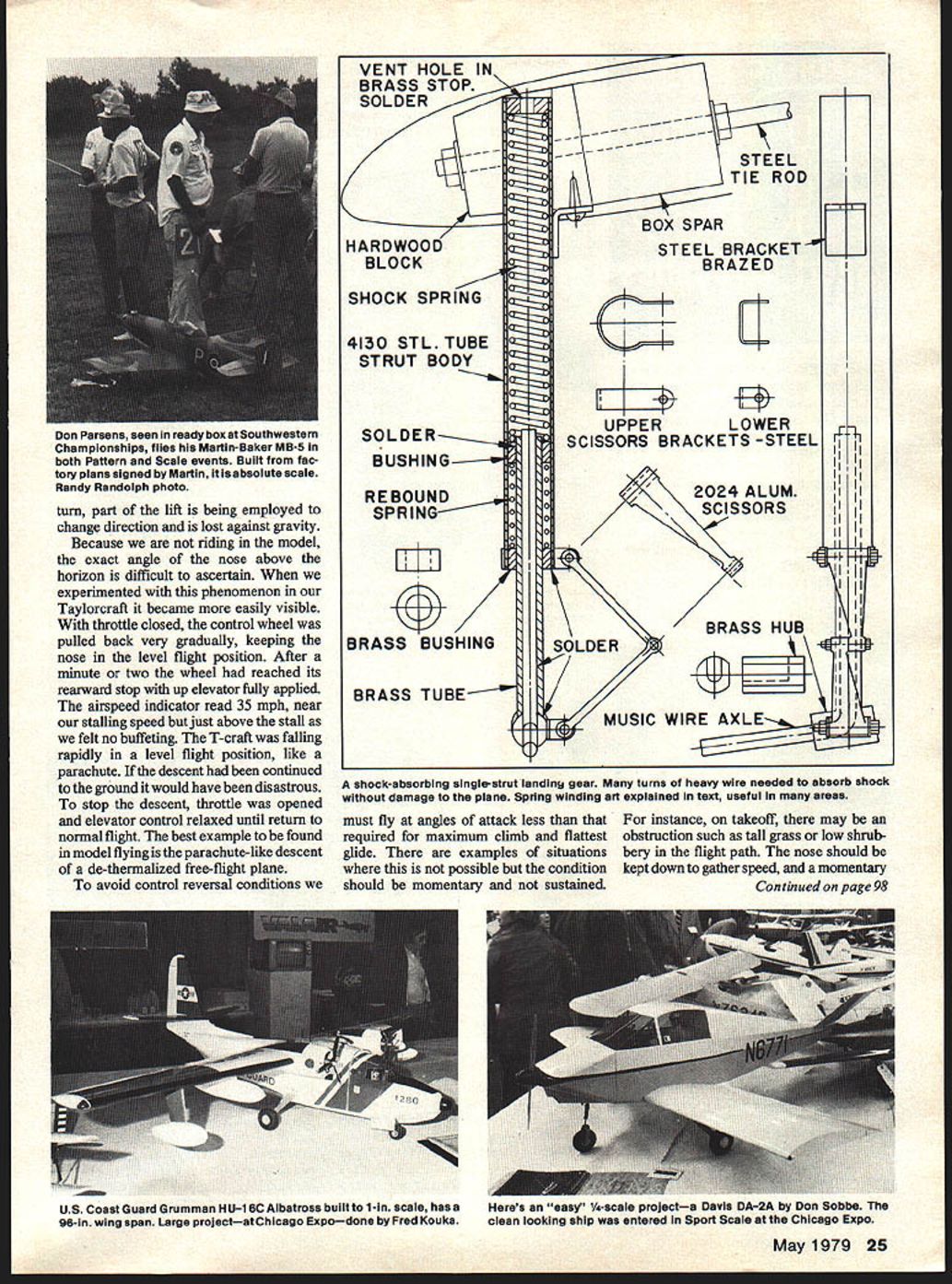
Single Strut Landing Gears
A scale model's best friend is a landing gear that will absorb shock without damage to structure. To devise such a gear it is best to follow full-scale practice, using coil compression springs to absorb both direct and rebound shock.
Preferred material for the strut body is thin-wall chrome-molybdenum 4130 steel tube of the type used in welded aircraft fuselage construction. Scrap lengths are usually obtainable from your friendly neighborhood airport fixed-base operator. The desirable size is .50-inch outside diameter with a wall thickness of .035-inch. Its retail price should be about $1.50 per foot. Other materials such as brass and lower grades of steel can be used, but their strength does not approach that of 4130 aircraft tubing.
The lower leg, which moves vertically within the strut body, is formed from .156-inch music wire, built up with brass tube to the proper scale diameter. A brass turning, made from rod, covers the wire bend and also serves as a mount for the lower scissors yoke. Scissors are filed from solid aluminum bar, preferably 2024 alloy for ease of machining and hardness. All four scissors parts are identical.
Springs are wound of music wire. Winding forces are greater than can be managed by hand. Our springs are wound on a mandrel chucked in a lathe, using the back gears to obtain the slowest possible winding speed. To wind springs by hand, the mandrel would need to be driven by a 6- or 8-inch long crank lever with the mandrel supported by substantial bearings clamped in a vise. The mandrel should be slightly smaller than the desired inside diameter of the spring because there will be some opening of coils after winding. A wire-size hole drilled through the mandrel secures the wire for starting the winding.
When winding manually, one person turns the crank while the second uses a vise-grip plier to apply maximum tension on the wire. Coils are laid with spacing that will result in the proper free length of spring when the desired number of turns has been reached. Spacing between adjacent coils is important in winding a spring with length to fit the strut body. Music wire is the hobby-shop variety. Be not discouraged if first attempts are not correct. Most of ours are made by the trial-and-error method. The only real trick is to get two sufficiently similar in length and number of turns for both landing-gear legs. Springs that are wound too short can be used by adding spacers or washers at one end, so it is wise to err in the short direction. If one spring has fewer turns than the other it can be used if the difference is 10% maximum. First and last turns should be wound with no gap between coils.
Example spring for a typical model:
- For .50-inch outside-diameter strut bodies on a plane weighing near ten pounds, a likely shock spring would be wound from .062-inch diameter wire on a .28-inch diameter mandrel, with 24 turns and a free length to fit the spring space plus .25-inch. This spring has a rate of 22.5 pounds per inch of deflection. When it is compressed into the strut with its mating rebound spring, it is preloaded by that .25-inch so that it will support the plane's weight without excessive deflection. In a hard landing it will compress a nominal 1.25-inch deflection to absorb a load of 28 pounds in a one-wheel landing, or 56 pounds for both wheels, or about 5-1/2 times the plane's weight.
- The lower rebound springs could be wound from .046-inch diameter wire on a .31-inch diameter mandrel with 6 turns and a free length to fit its space plus .25-inch. Its rate is about the same as that of the shock spring. If rebound springs are omitted, expect loud noises from the gear on each landing. Shock and rebound springs compress about equally in assembly, .25-inch.
For heavier planes use larger wire or fewer turns. Fewer turns will stiffen the spring and could lead to bouncy landings because of the higher spring rate. As an example, if the 24 turns is changed to 18, the rate in pounds per inch changes from 22.5 to 30.
Spring-rate formula
- Use the formula:
Load (spring rate) = (11,500,000 * d^4) / (8 * D^3 * N) where:
- 11,500,000 is the music-wire torsional modulus of elasticity,
- d = wire diameter (in inches),
- D = mean diameter of spring (O.D. minus wire diameter),
- N = number of turns,
- 8 is a constant.
With any electronic calculator it's a snap. Multiply the rate by the deflection to get the actual load of the spring at any point in its travel, beginning with the free length, keeping in mind that the spring is already partially loaded when assembled in the strut.
Wheel alignment and assembly
- Camber angle is the slight slope that brings tires closer together at the bottom, where they contact the runway, than at the top. When bending axle wires, camber angle, dihedral angle and 90 degrees are added to find the wire bend angle.
Assembly sequence:
- Silver-solder the brace steel bracket to the strut body.
- Solder the brass tube and hub (one right, one left) to the axle wire.
- Place one bushing and the rebound spring on the lower leg and solder the other bushing to the top end.
- Insert the leg into the strut body and solder the lower brass bushing into the body, making certain no solder creeps into the sliding fit with the leg.
- Solder the upper scissors bracket to the strut body in careful alignment with the brazed bracket.
- Insert the shock spring and solder a brass stop in the tube upper end. (A vent hole is required in the stop, or the strut will be a pneumatic shock absorber.)
- Assemble scissors and lower bracket with screws. Solder the lower bracket to the hub, then remove scissors and tap a short #2-56 screw into the lower bracket and hub to remove shear loads from the soft-solder joint.
Notes on materials and finishing:
- We prefer lead-tin 50-50 solder for all but the brazed steel bracket, because brazing heat will damage music wire.
- The stop at the tube top must be very securely soldered, as it carries considerable load from the compressed springs initially, and heavy final loads in a hard landing.
- The brass hexagon-head screws and nuts are hobby-shop items used by model railroaders, assembled with Loctite to prevent vibration loosening.
- Lubricate sliding parts with light oil.
Mounting struts in the wing:
- There should be solid material, such as plywood, in the main wing spar extending through the center section. A hardwood block with a .50-inch hole bored for the strut is epoxy-glued to the spar.
- Steel threaded rods go through blocks and spar, extending to a rear spar, spreading the load of rearward shocks.
- .156-inch diameter music wire, with thick washers or spacers soldered to the wire and epoxy-glued against the spar, are a husky substitute for threaded rods.
- Block and rods must be assembled early in wing construction. Most gears angle forward so that wheel centers are forward of the spar. A single wood screw will hold a strut in place in its socket.
Drawing Source
George H. Clapp is offering 1/20th-scale drawings of the full-size folding-wing 1927 Fairchild FC-2 along with photos for scale documentation. These are the same highly detailed drawings published in the March issue of Model Aviation but are full-size prints from his original. The additional photos will be useful in preparation of scale documentation. Send 25¢ and a self-addressed and stamped business-size envelope for list to: George H. Clapp, Box 115, Central Square, NY 13036.
Letters from Readers
In our February column we requested letters with questions from readers. We didn't expect the flood of correspondence that followed. Some was so highly technical as to be more than a little over our heads. The average question was concerned with the basics that bother many modelers. A surprisingly large percentage of letters were from other than RC Scale types, meaning that our material need not be addressed to those people alone. We would like to personally thank all who took time to write and hope, in the near future, to answer each letter by mail as well as through the column.
Bob and Dolly Wischer Rt. 1, S-221 Lapham Peak Road, Delafield, WI 53018.
Transcribed from original scans by AI. Minor OCR errors may remain.

