
Radio Control: Scale
Bob & Dolly Wischer
Fuel Lines
Letters from Frank Healey and Jack George inquire about methods of pumping fuel into a scale model with engine and tank completely enclosed in a cowling. Jack objects to the usual method of fumbling with needle-nose pliers, through a small opening, to remove the fuel tube from the carburetor and the equally objectionable replacement afterward. Quite possibly this problem has been solved in numerous ways by other modelers who would like to share their knowledge through this column.
On some installations it is a relatively simple matter to split the cowl so that its upper half is removable, exposing engine and tank for filling. We have used this method on our Douglas Mailplane, where a single machine screw is hidden in the dummy air intake to secure the cowl half. It is slightly inconvenient because the cowl must be removed for each flight, but the advantages are immediately evident:
- The tank is visible during filling, which helps prevent spilling raw fuel inside the tank compartment.
- Just before replacing the cowl, a finger can be placed over the carburetor air intake and the prop given a few flicks to prime the engine for easier starting.
- Muffler pressure and vent tubes need not be disturbed; the tank can be vented through the muffler during filling.
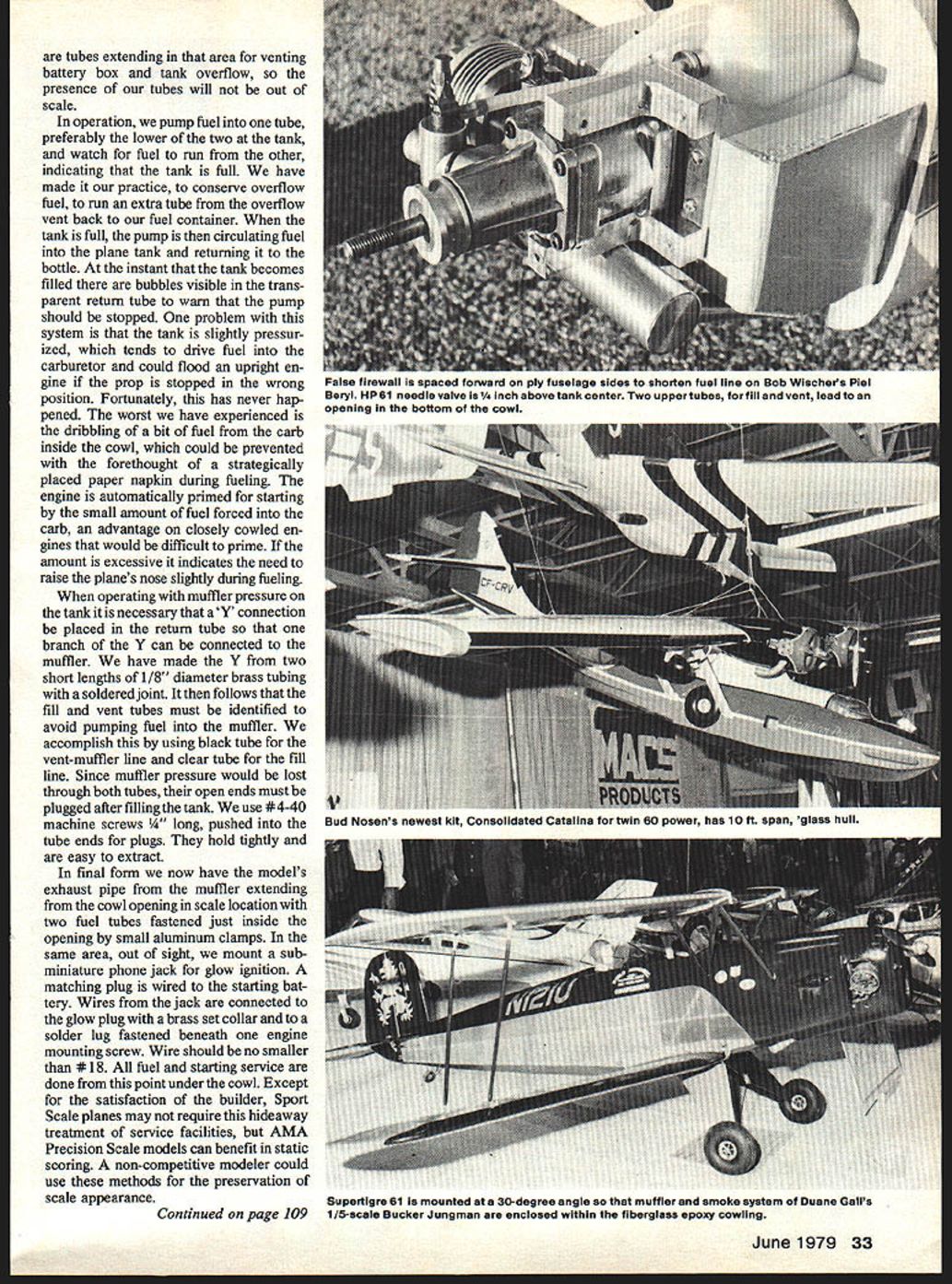
Where tank and engine are really buried and cowl removal is a major task, we have used another method with some success. A tank with three openings is needed, such as the Kraft tank. The usual tube runs from tank to carb. From the upper portion of the tank, parallel tubes run to a convenient opening at the cowl bottom for filling and venting. Vent tubes are equally effective regardless of the direction that they take from the tank and can run downward for any length. Most prototypes have exhaust and cooling air outlets that can be used for termination of vent tubes. Close examination of full-size planes will reveal tubes in that area for venting battery boxes and tank overflow, so the presence of our tubes will not be out of scale.
In operation, we pump fuel into one tube—preferably the lower of the two at the tank—and watch for fuel to run from the other, indicating the tank is full. To conserve overflow fuel, we run an extra tube from the overflow vent back to our fuel container. When the tank is full, the pump then circulates fuel into the plane tank and returns it to the bottle. At the instant the tank becomes filled there are bubbles visible in the transparent return tube to warn that the pump should be stopped.
One problem with this system is that the tank becomes slightly pressurized, which tends to drive fuel into the carburetor and could flood an upright engine if the prop is stopped in the wrong position. Fortunately, this has never happened to us; the worst experienced is a dribble of fuel from the carb inside the cowl, which could be prevented with a strategically placed paper napkin during fueling. The engine is automatically primed for starting by the small amount of fuel forced into the carb—an advantage on closely cowled engines that would be difficult to prime. If the amount is excessive it indicates the need to raise the plane's nose slightly during fueling.
When operating with muffler pressure on the tank it is necessary to place a "Y" connection in the return tube so that one branch of the Y can be connected to the muffler. We have made the Y from two short lengths of 1/8" diameter brass tubing with a soldered joint. It then follows that the fill and vent tubes must be identified to avoid pumping fuel into the muffler. We accomplish this by using black tubing for the vent-muffler line and clear tubing for the fill line. Since muffler pressure would be lost through both tubes, their open ends must be plugged after filling the tank. We use #4-40 machine screws, 1/4" long, pushed into the tube ends for plugs. They hold tightly and are easy to extract.
In final form we now have the model's exhaust pipe from the muffler extending from the cowl opening in scale location with two fuel tubes fastened just inside the opening by small aluminum clamps. In the same area, out of sight, we mount a subminiature phone jack for glow ignition. A matching plug is wired to the starting battery. Wires from the jack are connected to the glow plug with a brass set collar and to a solder lug fastened beneath one engine mounting screw. Wire should be no smaller than #18. All fuel and starting service are done from this point under the cowl.
Except for the satisfaction of the builder, sport-scale planes may not require this hideaway treatment of service facilities, but AMA precision-scale models can benefit in static scoring. A non-competitive modeler could use these methods for the preservation of scale appearance.
Tank Location and Engine Mounting
When the model's fuel tank would otherwise be located in the space normally occupied by people (cockpit), we extend the fuselage basic structure forward to a false firewall immediately behind the engine, using short aluminum engine mounts. The cowl then extends rearward to cover the protruding frame. In addition to supplementing rigidity, this permits the fuel tank to be carried within the basic fuselage box to a point very close behind the engine, keeping the fuel line as short as possible. A short fuel line will do more for reliable engine runs than any single item, other than adding a pump.
In the past, when a standard model tank would be visible in the cockpit, we have made special tanks. Using .005" shim brass for lightness, these were assembled by soldering. The tank could then be made to a shape similar to that of the prototype and placed out of view under the front deck. It should be kept in mind that model fuel will erode brass and the tank must be completely emptied after each flying session. A standard silicone rubber tube with clunk weight is sealed permanently inside by soldering the rear of the tank into place as the last operation. The thin brass is very easily soldered.
For maximum scale appearance a large-diameter brass tube can extend from the tank top in the scale filler location, with a neoprene stopper to assure air tightness for muffler pressure. Scale fillers are a practical impossibility with standard plastic tanks. Using a scale filler spout requires extreme care since over-filling will spill raw fuel on exterior surfaces or into surrounding spaces, where oil is absorbed to become permanent. For this reason it cannot be recommended; we have never been tempted to use it even though we are often asked if our dummy fuel caps are functional.
A completely sealed .005" brass tank gives an audible "oil-can" sound when it reaches maximum capacity during filling. This can be an effective indicator—except when your flightline neighbor is tuning his engine.
A disadvantage in mounting the fuel tank near scale location in a fuselage is that it will likely be too high above the engine needle valve. This could result in a flood of fuel inside the cowl if the engine is not started immediately after filling the tank, especially with planes having tricycle landing gear and near-level fuselage.
The ideal tank location is not always easily achieved in scale models. When designing a model, we prefer to consider engine mounting and tank location in the early development stages as one of the first items shown on the initial layout. The model structure is then drawn around the tank with its center 1/4" to 1/2" below the needle valve. Side and near-inverted engine mountings often afford advantages because the tank can then be installed in a more convenient, lower position in the fuselage. A vertical inverted engine should be avoided as it presents difficulties in starting, due to a drowned glow plug. We often see modelers holding a plane inverted to get the engine upright for starting. An engine set ten or more degrees to the right of vertical will not have this problem and has the additional benefit of placing the muffler nearer the plane centerline for easier concealment.
From inverted to upright, the engine can be swung through an arc of about 170 degrees to help find the ideal tank level location as well as fitting the cowl shape. If cost is no obstacle, the Perry and Robart pumps are practical solutions that permit tanks to be located in any manner.
There is really no good reason for an engine to stick straight up through the cowl of a scale plane, spoiling the shape of the nose. The front quarter of a model's appearance is crucial to preserving the prototype contour. Any change in nose shape will destroy the illusion of shrunken reality. When we choose a plane to model, the real reason often has something to do with the nose. We cannot spend up to a year duplicating in miniature a plane with an ugly or untidy nose. The old argument that an inverted engine is hard to start is not sufficient reason, now that we know the simple solution of angle mounting and the benefits derived—particularly in tank location. The whole airplane suffers when the nose section lacks authenticity.
Bob and Dolly Wischer Rt. 1, S-221 Lapham Peak Rd., Delafield, WI 53018.
Wing Construction
Sheeting—if an extra tip was made to be used as a drawing curve—the tip sheeting blending is fun to do.
The construction of wing and tip on the jig and spacer blocks gives good alignment and will support some trimming and sand blending. With both panels finished (top only), saw cut the rib webbing that will allow center section plywood gussets to be installed. Trim the spars for proper dihedral angles; line up the root rib (wing upside down) with the edge of the working surface, block up leading and trailing edges, and weigh down. Slide the plywood extensions down and inward. Check and adjust fit before adding glue.
When the alignment and fit check out, add thin coats of adhesive and slide into position. Repeat the process on the other panel. Clamp and pin until dry. Add the landing gear blocks and support ribs. Drill small holes for landing gear hold-down straps. Install gear and clamps, coat with epoxy. Finish the wing by adding the lower tips, spar webbing, sheeting, and cap strips. Carve, plane, file, and sand-blend to finish. The joining of the wing sections requires careful attention and step planning.
Tail Surfaces
The rudder/fin and stabilizer/elevator are sandwich balsa/plywood core structures. The laminated outlines add stiffness and resist denting better than a single-grained horizontal structure. They are also easier to sand and shape. The outline allows use of soft balsa for filler shape. The lightened plywood core carries the hinge and fin extension slot, which improves alignment and strength.
Refer to the instruction sheet on how the structure is accomplished. Prepare these assemblies so that the outline profile can be sawed out after the glue-ups are finished, ensuring perimeter edge squareness. A length of 1/16" dia. music wire works very well as a hinge gap spacer tool. The tail brace (1/4" dowel) holes are pre-drilled and used as alignment keys. Also, draw (with ballpoint) center lines for alignment. Use the prefinished, saw-cut outline as the template to wrap around the laminated part of the structure. Complete all sandwiching and laminating before shaping and sand-blending. Try to pick at least medium-hard (1/16" x 1/4") straight-grained balsa for all laminating. Wet pieces only in areas that require tight radius bends. Use soft-light 3/32" sheets on each side of the 1/64" plywood core as allowance for sanding.
Prior to hinging and assembly to the fuselage, separate the surfaces at the hinge line using a small saw or straightedge with several passes of a knife blade. Sand the edges and round where required. Add the brace wire and 3/16" dia. hardwood dowels. Slip these in and out, sanding them until they are flush before gluing them into place. The 1/16" holes are pre-drilled through the dowels, or drilled just prior to final sanding.
Finishing
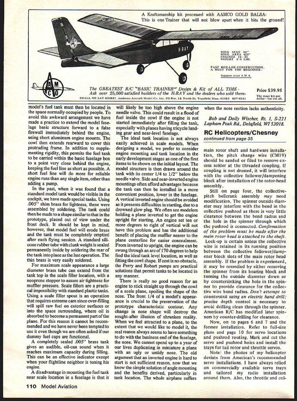
My plane was covered with MonoKote, including clear over the cabin—overall white, with orange as the secondary color, and black trim tape separating the colors. Cabin doors are outlined with 1/32" black tape. Spray over color and tapes with clear enamel.
My model (dry) weighs just under 4 lbs.; the bare airframe (with landing gear wires) is near 2 lbs. A 4- or 6-ounce nylon tank can be used; however, the 6-ounce must be rotated 90° and is a slide fit. Engine is a Max .30 with muffler. Robart wheels are narrow enough to fit the pants well.
I used the World Engines Expert radio with S10 servos. No servo relocation was required to adjust the center of gravity from the plan location. Using similar-size equipment and power should not require any shifting of components. Make sure the nose does not balance above the horizontal when the plane is supported at the C.G. position.
Adjust the control surfaces as follows:
- Ailerons: 3/16" up and down
- Rudder: 40° right and left
- Elevator: 30° to 40°
I used heavy monofilament for the tail brace with a spring to retain tension. The landing gear shock struts and the wing struts add to the appearance and should not be overlooked. Since they are removable, they will be easy to add for show and remove for flying.
CREDITS
I wish to give credit and thanks to the following people for responding with helpful background information:
- Mr. Louis S. Casey, Curator of Aircraft, National Air and Space Museum, Smithsonian Institution, Washington, D.C.
- Patti Schaft, Wright-Patterson Air Force Base, Air Force Museum
Photography by: Tim Miskell, P. Jessee. Outdoor pictures by Bob Jolly.
I surely hope you enjoy building the Coupe. The construction, though in places a little different, is worthy of your best craftsmanship. If you have a particular problem and wish to correspond, send inquiry to J. Jessee, 890 Fairview Ave., D202, Bowling Green, KY 42101.
Transcribed from original scans by AI. Minor OCR errors may remain.

