
RADIO CONTROL: Scale
Bob & Dolly Wischer
Photo documentation
Knowledgeable contest judges, given the choice between details and shapes shown on a three-view drawing and those shown in photos, will usually take photos as the more reliable information source. Three-view drawings have fooled many modelers; unless hard dimensions are provided, drawings alone often cannot establish the exact shapes, sizes and positions needed for a superior plane.
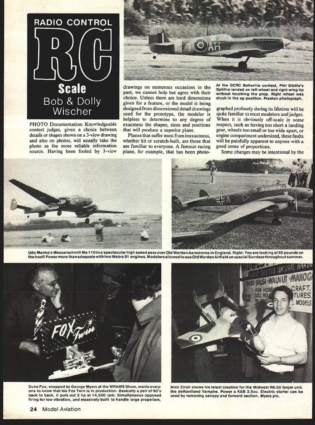
Planes that suffer most from inexactness are those familiar to everyone. A well‑photographed racing or wartime plane will be easily recognized, and faults such as too-short landing gear, wheels that are too small or too far apart, or an undersized engine compartment will be painfully apparent to anyone with a good sense of proportion.
Some changes are intentional to improve flight characteristics. In Sport Scale it is common to increase wing and tail area; these changes are usually easy to detect at normal viewing distance. Shortening the landing gear on a WWII fighter, however, may improve handling yet be a serious appearance handicap — the static score penalty must be offset by the flight/ground‑handling score to be worthwhile.
Photos can correct glaring drawing errors if the camera is properly positioned to minimize distortion. Several recent models were built using an abundance of photographic data plus factory drawings when available. A model built from three‑views and published photos can still be frustrating if the photographic record is thin — successful modeling often depends on experience and imagination as well as documentation.
Everything depends on the modeler’s viewpoint. Some are satisfied with a scale‑like bird that flies well and need little documentation. Others research exhaustively — traveling to see the prototype, measuring, sketching and photographing every detail before cutting balsa. Most modelers fall between these extremes: the airplane is foremost and documentation secondary. A good set of photographs records detail for construction and forms the nucleus of the scale presentation to prove authenticity in competition.
- Sport Scale contestants are limited to a maximum of six pages of documentation.
- Precision Scale has no strict quantity limit, but avoid confusing judges by including too many photos or photos of details not reproduced on the model.
- Choose a subject you can thoroughly photograph; remove mysteries where possible and, if feasible, have access to the prototype during construction.
Design stage & photography techniques
When photographing a prototype for scaling and detailing, we use 35 mm black‑and‑white film for most structural and detail work, reserving color film only for finishes, colors and markings. We buy bulk film rolls to reduce cost, spool them into cartridges in total darkness, and develop fine‑grain negatives so large enlargements show detail. Two 36‑exposure rolls usually cover every area, including interiors. Black‑and‑white negatives cost roughly a few cents per frame; 5 × 7" prints made at home are inexpensive. The expensive part is traveling to find the prototype.
Practical photographic guidance:
- Take overall views of both sides, front and rear for general arrangement. A top view is valuable but often impractical.
- Wear coveralls so you can photograph from ground level — much detail is hidden on airplane bottoms.
- Avoid wide‑angle lenses when taking photos for measurement: they can introduce perspective distortion. Use normal or longer focal lengths. Wide angles are useful only in confined interiors.
- Direct views (surface parallel to the film plane) are most useful for determining dimensions. If one absolute dimension is known in the photo, all other features in that enlargement will be in proportion and can be measured mathematically.
- Example: a front-facing cowl photo with a measured overall width allows measurements of cowl opening, spinner diameter, screw locations, and prop dimensions from the enlargement.
- Example: a direct side view, along with overall fuselage length, can locate insignia, trim areas, openings, steps and stringers without measuring each detail on the prototype.
- When direct views cannot be taken, supplement with freehand sketches and measured dimensions. For example, to replicate added wheel pants, use a side view with one overall dimension plus interior photos for mounting details.
These methods may seem elementary to experienced modelers, but beginners often need step‑by‑step guidance for scaling from photos.
Control surface flutter
Flutter can be catastrophic and is not limited to full‑size aircraft. A historical example: when Jimmy Doolittle pushed speed limits in a Travel Air Mystery S, severe aileron flutter occurred — one aileron departed along with part of the wing. The Travel Air had over‑balanced frise ailerons (hinge line too far rearward) and too‑flexible torque tubes.
Signs and causes:
- Flutter often manifests as a buzzing or humming sound from the ground. Repeated events will weaken hinges and linkages.
- Common contributors:
- Flexibility in torque tubes or pushrods.
- Long, soft ailerons that twist easily.
- Bellcranks positioned at one end of a long surface rather than near the center.
- Soft linkages, sloppy pivots, or servos mounted too flexibly (e.g., loose rubber grommets).
- Loose covering can also contribute to wing flutter at higher speeds.
Remedies:
- Reduce flexibility in control runs: use large torque tubes (never less than 1/4" diameter; larger for long runs) when appropriate.
- For pushrod/bellcrank systems, reduce clearance in all pivots; do not over‑drill bellcrank holes in the name of free movement.
- Use firm servo mounts; eliminate play in linkages.
- Seal aileron gaps with narrow tape to stop airflow through the gap when appropriate (may affect scale appearance).
- For tail surfaces, use strong pushrods, eliminate play and mount servos firmly.
Even wings without ailerons can flutter if built too lightly and exposed to excessive speed. Examples include a 90" span wing tearing off due to inadequate covering tension and cases of rudder or elevator flutter tearing hinges out of plywood. The sure cure is to build stiffness and minimize play in control systems.
Parts catalog
For mechanisms to operate gun turrets, canopies, landing gear and other scale gadgets, industrial catalogs are invaluable. Stock Drive Products and similar suppliers list thousands of useful parts for scale modelers, including:
- Rack and pinion drives (brass, steel, lightweight nylon) for straight‑line motion.
- Spur and needle bearings, pinion gears and shafts.
- Couplings, splines and miniature shafts.
- A variety of miniature electric motors used in appliances and instruments.
These components require imagination and careful selection for weight and strength, but they greatly expand possibilities for realistic, reliable scale mechanisms.
Transcribed from original scans by AI. Minor OCR errors may remain.

