
Radio Control: Scale
Bob & Dolly Wischer
Wire Bracing
Models of modern aerobatic biplanes — such as:
- Pitts
- Smith Miniplane
- Christen Eagle
- EAA Acro
- Acroduster
— will fly without bracing wires. In fact, adding wires induces drag that slows the plane and makes it less aerobatic. Wires are largely a cosmetic enhancement to appease the guilty feeling that a plane looks naked without them. The ample thickness of wings on modern biplanes is sufficient for the deep spars needed to carry the weight, and foam wings also have great strength.
Models of antique, wire-braced planes will most likely need wires to keep fragile, thin wings from fracturing during abrupt maneuvers. In our experience, flying wires that carry aerodynamic loads while the plane is airborne need to be inelastic so incidence angles will not change with aileron action. Landing wires that support the wings when wheels make contact with the ground need some resiliency to absorb the shock of an occasional bad landing. This has often resulted in torn wires or, more frequently, a wire anchor ripped from its mounting. We now use springs in the landing wires.
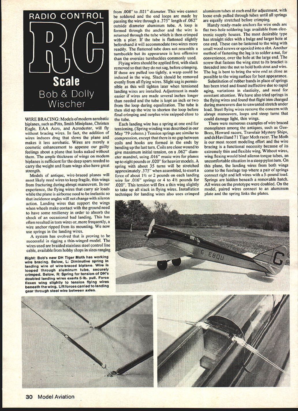
A system has evolved that is proving successful for rigging thin-winged models. The wires used are braided stainless steel control-line cable, available from hobby shops in sizes ranging from .008" to .021" diameter. This wire cannot be soldered; end loops are made by passing the wire through a 0.375" length of 0.062" outside-diameter aluminum tube. A loop is formed through the anchor and the wire is returned through the tube, which is then crimped with pliers. If the tube is flattened slightly beforehand it will accommodate two wires more readily. The flattened tube does not resemble a turnbuckle, but its appearance is less offensive than the oversize turnbuckles commonly used.
Procedure and tips:
- Apply flying wires first, removing slack so they do not sag, before crimping. Do not pull them too tight or a warp could be induced in the wing. Remove slack evenly from all flying wires. Slight sag is permissible since this will tighten later when tensioned landing wires are installed.
- Make wires several inches longer than needed and keep the tube an inch or two from the loop during equalization. Slide the tube up the wire to shorten the loop before final crimping and snip surplus wire close to the tube.
- Each landing wire has a spring at one end for tensioning. (Spring winding was described in our May '79 column.) Tension springs are similar to compression springs except there is no gap between coils and hooks are formed in the ends by bending up the last turn. Coils are close-wound to give maximum initial tension, wound on a 0.062" diameter mandrel, using .016" music wire for planes up to eight pounds or .020" for heavier models.
- A spring with about 35 turns will be stretched approximately .375" when assembled, exerting about 1½–2 pounds on each landing wire for .016" springs or 4–4½ pounds for .020" springs. This tension will flex a thin wing slightly to take up all slack in flying wires.
- Installation technique for landing wires also uses crimped aluminum tubes at each end for adjustment, with loose ends pulled through tubes until all springs are equally stretched before crimping.
Handy ready-made anchors for wire ends are flat two-hole soldering lugs available from electronics supply houses. The most desirable type has straight sides with a bulge and a larger hole at one end. These can be fastened to the wing with small wood screws or epoxied into a slot. Another method is to solder a nut over the hole at the large end; the screw that fastens the wing strut to its bracket is threaded into the nut to hold both strut and wire. Bend the lug to bring the wire end as close as possible to the wing surface for best appearance.
Substitution of rubber bands in place of springs has been tried and found ineffective due to rapid aging, variations in elasticity, and the need for constant attention. We have also tried springs in the flying wires and found that flight trim changed during maneuvers due to unwanted stretch under load. Steel flying wires remove the concern with abrupt maneuvers, loops, and steep turns that could damage light, thin wings.
There were numerous examples of wire-braced monoplanes among the antiques, such as:
- Gee-Bees
- Howard racers
- Travel Air Mystery Ships
- de Havilland 71 Tiger Moth racers
The Tiger Moth is our most recent modeling effort and the wire bracing is a functional necessity because of its extremely thin and flexible wing. Without wires, wing flexing would bind aileron torque tubes — an uncomfortable situation in a steep pylon turn. On this plane, the landing wires from both wings come to the fuselage top where a pair of springs connect right and left wires with a 5-pound load. Springs are hidden beneath a removable hatch. All wires on the prototype were doubled. On the model, paired wires connect to an aluminum plate and the spring links the plates.
Control cables of full-size planes use a similar method for forming loops in cable ends. A steel sleeve is swaged over the braided cable, producing a joint of great strength. In modeling practice, the soft aluminum tube's interior surface is swaged into the braided cable's convolutions in the process of crimping to make a joint of surprising strength.
Spring Source
A letter from Phil Mahony, gunsmith and modeler in Lime Rock, CT, informs us that there are many things in common between the two hobbies. Spring makers who specialize in the needs of gunsmiths have large stocks of springs in sizes most useful to modelers.
- W. C. Wolf Co., P.O. Box 232, Ardmore, PA 19003 is a spring maker for gunsmiths.
- Products are also available through a distributor, Bob Brownell, Route 2, Box 1, Montezuma, IA 50171.
Phil says the Brownell catalog is loaded with tools that are ideal for modeling purposes: wood carving tools, pliers, pin punches and vises.
Tail Surface Areas
Not too long ago the ideal prototype would have been a plane with large tail surfaces, and modelers often increased area to promote stability. With proportional control the model can be flown like the full-size plane, and the practice of enlarging surfaces — a hold-over from our free-flight days — has diminished. In fact, we find that the opposite may be more desirable, with large horizontal surfaces considered detrimental.
Our venerable, 11-year-old Sopwith 1½ Strutter was thought to be ideal because of its monstrous stabilizer and elevator, and its flight stability is excellent. However, during landings we find it impossible to bring the tail low enough for a complete stall because the elevator will not overcome the ground-cushion effect beneath the stabilizer. The landing flare continues on and on across the field, just above stalling speed. Because directional control with ailerons and rudder is poor near stall, the model wanders wherever each vagrant wind gust will carry it. The model's only successful landings are tail-high and realism suffers.
Some of the Strutters had very broad flaps at the root of the lower wings (not employed on our model), probably necessary to pass through the stall point as quickly as possible to stop the endless drift across the landing field.
RC Scale / Wischers (continued from page 31)
Our club field is attached to a local flight strip. One of our members brought his full-size Varga Kachina (Shinn 2150A) to the strip and we examined the plane as a possible scale project. He mentioned its tiny tail surfaces as being a liability because the nose wheel could not be lifted for takeoff (rotation) until considerable speed had built up. What appeared at first to be detrimental is actually a desirable feature, since the plane must have flying speed before liftoff. The chances of its settling back on the tail at takeoff or landing are less.
We have had similar experiences with some scale models that have small tail surfaces. The de Havilland racer mentioned earlier is an example. Old-time modelers, seeing its tiny tail feathers, cast doubt on its stability. This has not proven to be the case, however; our model's handling near stall has been exemplary. When pitch stability problems have occurred on other models it was the result of overly sensitive elevators with greater travel than necessary.
Bob and Dolly Wischer Rt. 1, S-221 Lapham Peak Road, Delafield, WI 53018.
Transcribed from original scans by AI. Minor OCR errors may remain.

