
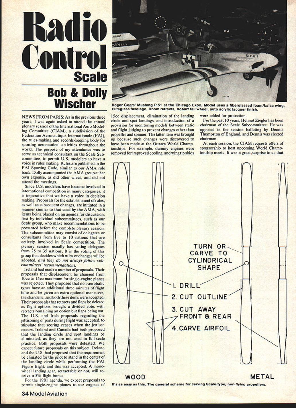
Radio Control: Scale
Bob & Dolly Wischer
News from Paris
As in the previous three years, I was asked to attend the annual plenary session of the International Aero Modelling Committee (CIAM), a subdivision of the Fédération Aéronautique Internationale (FAI), the rules-making and records-keeping body for sporting aeronautical activities throughout the world. My purpose was to serve as technical consultant on the Scale Subcommittee so U.S. modelers would have a voice in rules making. Rules are published in the FAI Sporting Code, similar to our AMA rule book. Dolly accompanied the AMA group at her own expense and did not attend the meetings.
Since U.S. modelers have become involved in international competition in many categories, it is imperative we have a voice in decision making. Proposals for establishment of rules and subsequent changes are initiated much as with the AMA: items are placed on an agenda for discussion, first by individual subcommittees (such as our Scale group), which make recommendations to be presented before the complete plenary session. The subcommittee may consist of delegates or consultants from five to ten nations actively involved in Scale competition. The plenary session usually has voting delegates from 25 to 35 nations. That voting group decides which rules or changes will be adopted, and they do not always follow subcommittee recommendations.
Ireland made a number of proposals. Decisions and actions included:
- A proposal to change maximum displacement for single-engine planes from 10 cc to 15 cc was rejected.
- A proposal to grant non-aerobatic types an additional three minutes of flight time and an extra optional maneuver (the chandelle) was accepted.
- Proposals to delete retracts and flaps as flight options drew a divided vote; retractable gear will remain an option, but flaps were removed as an option.
- A U.S./Irish proposal regarding jettisoning of parts was accepted: scoring ceases when a jettison occurs.
- Proposals from Ireland and Canada to eliminate the landing circle and spot landings (as not used in full-scale practice) were defeated; we expect further proposals on this subject.
- A proposal from Ireland and the U.S. to eliminate the requirement that the pilot stand in the center of the landing circle while performing the FAI Figure Eight was accepted.
- A monowheel landing gear, retractable or not, will receive a 5% flight bonus.
For the 1981 agenda we expect proposals to:
- Permit single-engine planes to use engines of 15 cc displacement.
- Eliminate the landing circle and spot landings.
- Introduce a provision for monitoring models between static and flight judging to prevent changes other than propeller and spinner. (This was raised after changes were discovered at the Ottawa World Championships—e.g., dummy engines removed for improved cooling and wing-tip skids added for protection.)
For the past 10 years Helmut Ziegler has chaired the Scale Subcommittee. He was challenged in the session balloting by Dennis Thumpston of England; Dennis was elected chairman.
At each session, CIAM requests offers to sponsor upcoming World Championship meets. It was a surprise that the offer for the 1982 Scale meet came from the USSR, with Kiev as first choice and Kharkov and Simferopol as alternates. Since no other national aero clubs offered, the USSR will likely host unless another nation makes a better offer. The USSR proposes events for F4B, Control Line, and F4C (Radio Control only), without a Stand-off Scale event. When a show of hands was requested for nations likely to send teams, ten nations indicated RC and seven CL. The absence of Stand-off will be a problem for some national aero clubs, including the AMA, which will be selecting teams in 1981 for the following year's championship. (Payment of team selection fees, and an FAI stamp on the AMA license, are required of team candidates.) If the USSR offer stands alone, there is no need to select a Stand-off team. If another national aero club makes an offer, including Stand-off Scale, in December 1981, we would need to select a team by some method other than the Nats.
Full-scale exchanges and visits
One reward of these trips is exchanging information with people who can tell us about the planes we model. On the western-most tip of southern England, near Land's End, there is an airport operated by Vivian Bellamy and his son. They build full-scale reproductions of historic airplanes. In one of their hangars we found a recently completed Sopwith 1 1/2-Strutter. Mr. Bellamy challenged us to find anything about the plane that was not authentic.
The Strutter had been flown, and his description of flight characteristics matched those of our model. The tail can't be lowered for a three-point landing. To help solve this problem, the Sopwith has large flaps at the lower wing roots that move upward at a steep angle, rather than downward. This feature was known to us but hard to believe until seen.
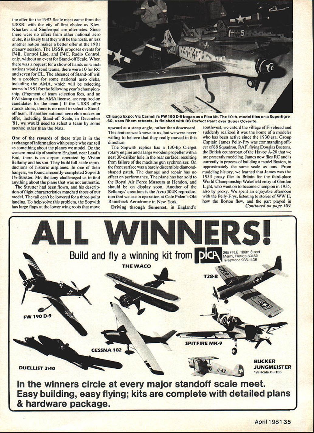
The Sopwith replica has a 130-hp Clerget rotary engine and a large wooden propeller with a neat .30-caliber hole in the rear surface, resulting from failure of the machine-gun synchronizer. On the front surface was a barely discernible diamond-shaped patch. The damage and repair had no effect on performance. The plane has been sold to the Royal Air Force Museum at Hendon and should be on display soon. Another Bellamy creation is an Avro 504K reproduction similar to the one seen at Cole Palen's Old Rhinebeck Aerodrome in New York.
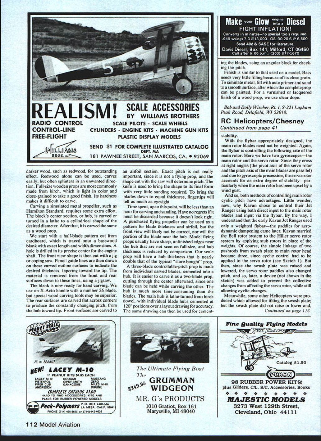
Driving through Somerset in England's southwest, we entered the village of Pivchard and realized it was the home of a modeller active since the 1930s. Group Captain James Pelly-Fry was commanding officer of 88 Squadron, RAF, flying Douglas Bostons—the British counterpart of the Havoc A-20 that we are presently modeling. James now flies RC and is building a model Boston to approximately the same scale as ours.
From modeling history, we learned James was the 1933 proxy flier in Britain for the third-place World Championship Wakefield entry of Gordon Light, who went on to become champion in 1935, also by proxy. We spent an enjoyable afternoon with the Pelly-Frys, listening to WWII stories, how the Boston flew, and the part played in bombing raids by the Douglas.
James has had considerable success with the stall-actuated slots on his powered RC glider; there is an audible clicking as they pop in and out during stall and recovery. There is a constant flow of Royal Navy jet and helicopter traffic over the Pelly-Fry home from the nearby Naval Air Station at Yeovilton, where the Fleet Air Arm Museum is located. Planes overhead included Hawker Hunters, Harriers, and English Electric Canberras. The next morning we revisited the museum, which has been expanded to house the British 002 Concorde prototype and two research aircraft used in its development.
Scale props
Most Scale modelers recognize the need to dress up a plane with a display propeller to improve appearance when it is not being flown. A few purists insist the scale prop must also fly the plane; there are successful examples, even adjustable-in-flight. One of the most frequently asked questions at static displays is whether the model would fly with the static prop. The answer depends on several factors.
- Some scale props are carved left-hand for early planes or modeled after planes with automobile engines, which rotate in the opposite direction; these obviously could not fly the model.
- For best performance with modern glow-plug engines, the scale prop should be replaced with one that matches engine performance.
- A less obvious reason many scale props can't be used as flying props is the absence of a prop nut: the scale prop often isn't fastened securely, and the center hole is drilled slightly undersize to thread onto the engine shaft.
Carving a prop is not difficult if you use a material that carves easily. We prefer basswood for two reasons: it has little grain, so the knife follows the intended cut rather than a strong grain, and it is readily available. Most hobby shops stock Midwest or Northeastern basswood planks. It can be laminated with a darker wood, such as redwood, for outstanding effect. Redwood alone carves easily but often splinters unpredictably. Full-size wooden props are most commonly made from birch, which is light in color and close-grained for a good finish; its hardness makes it difficult to carve.
To simulate a metal propeller (e.g., Hamilton Standard), the block's center section or hub is carved or turned in a lathe to a cylindrical shape of the desired diameter; after that it is carved like a wood prop.
Our carving method:
- Start with a half-blade pattern cut from cardboard, traced onto a basswood blank with exact length and width dimensions.
- Drill a hole in the precise center for the engine shaft.
- Cut the front-view shape with a jig or coping saw.
- Draw pencil guide lines on the curved outline surfaces to indicate desired thickness, tapering toward the tip.
- Remove material from the front and rear surfaces down to these lines, using a jigsaw.
- Hand-carve the blank to shape. We use an X-Acto handle with a No. 26 blade, though special wood-carving tools may be superior. Carve the rear surfaces flat across corners to produce the constantly changing pitch from hub to tip; carve the front surfaces to an airfoil section. Exact pitch is not critical for a non-flying prop—the initial saw shape will largely determine pitch.
- Bring the shape to final form with minimal sanding; fingertips tell blade thickness as much as eyesight.
Time spent up to this point will often be less than an hour for carving and sanding. Discard and retry if it doesn't look right. A purchased flying propeller can be used as a pattern for blade thickness and airfoil, but the front view and hub region will likely differ. Model flying props usually have sharp unfinished edges near the hub that are not seen on full-size props; hub thickness on a scale prop will be nearly double that of a typical store-bought prop.
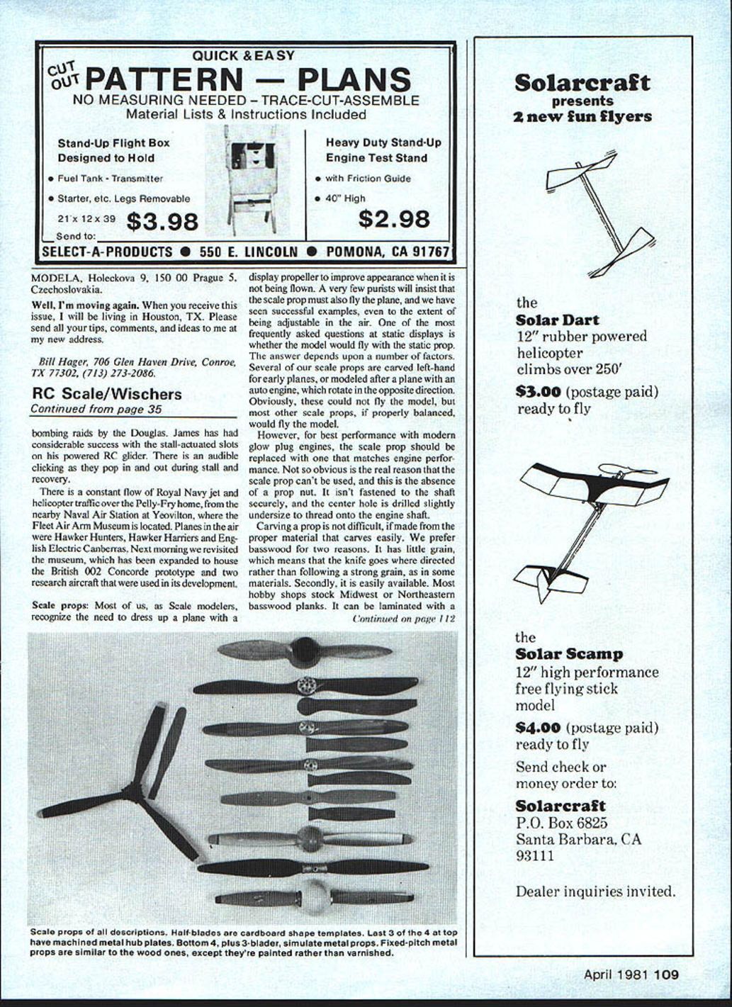
For a three-blade controllable-pitch prop, carve individual blades and cement them into a hub. It is easier to carve as a two-blade prop, then cut through the center afterward so one blade can be held while carving the other. The hub is more time-consuming than the blades: lathe-turn the main hub from birch dowel, cement individual blade hubs at 120° positions over a layout drawing for accuracy, then cement the blades, using an angular block to check pitch.
Finish:
- Basswood needs very little filling because of its close grain.
- To simulate metal, fill with auto primer and sand to a smooth surface, then paint.
- For a varnished or lacquered wood finish, use clear dope.
Bob and Dolly Wischer Rt. 1, S-221 Lapham Peak Road, Delafield, WI 53018.
Transcribed from original scans by AI. Minor OCR errors may remain.

