
Radio Control: Scale
Bob & Dolly Wischer
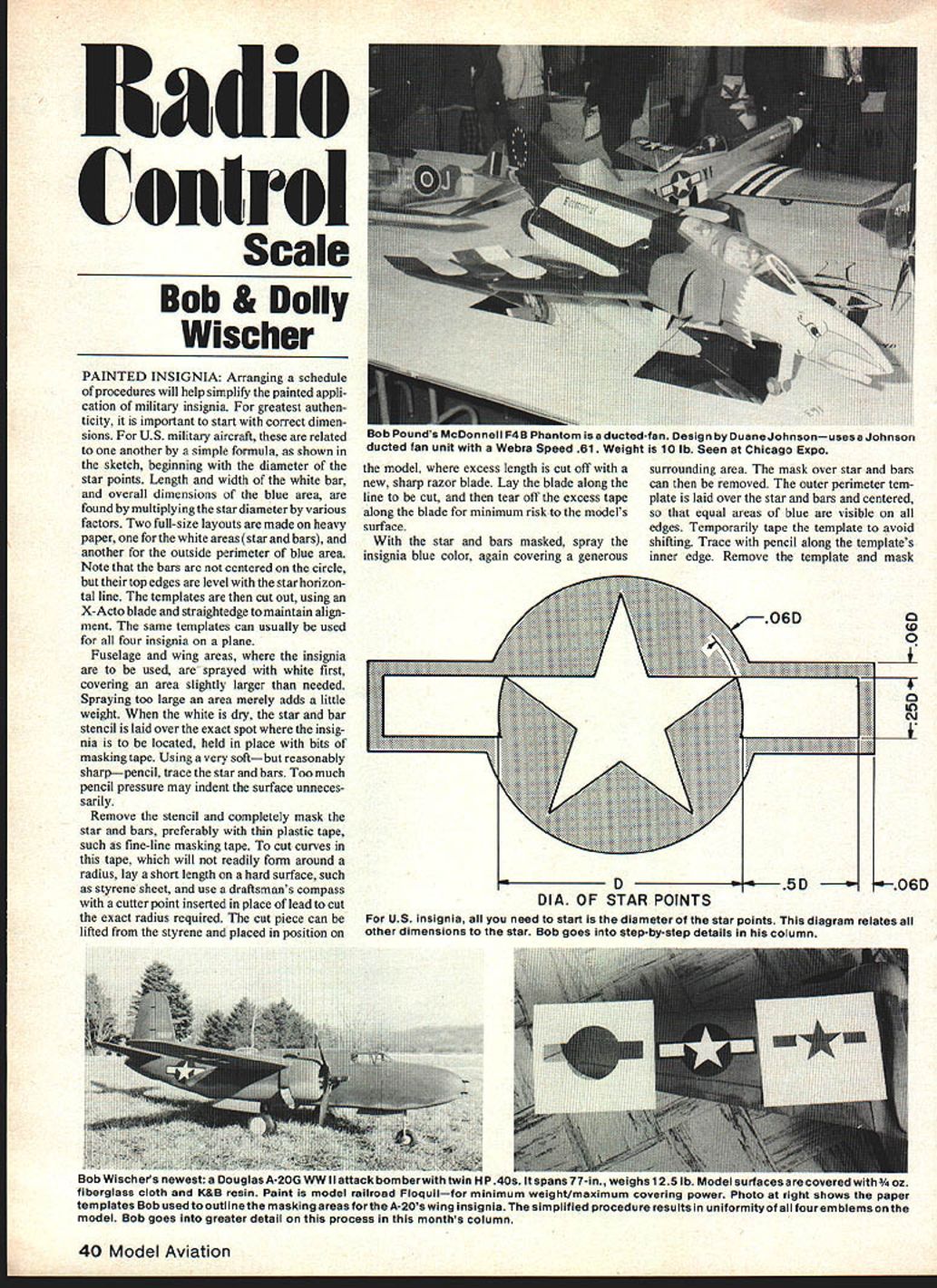
Painted Insignia
Arranging a simple schedule of procedures will simplify the painted application of military insignia. For greatest authenticity, start with correct dimensions. For U.S. military aircraft these are derived by a simple formula beginning with the diameter of the star points; lengths and widths of the white bars and the overall blue area are found by multiplying that star diameter by various factors. Two full-size layouts should be made on heavy paper: one for the white areas (star and bars) and another for the outside perimeter of the blue area. Note that the bars are not centered on the circle; their top edges are level with the star horizontal line. The same templates can usually be used for all four insignia on a plane.
Templates are cut out using an X-Acto blade and straightedge to maintain alignment. Use thin plastic tape (such as fine-line masking tape) to mask the star and bars; thin tape conforms better and reduces paint bleed.
To cut curves in masking tape that will not readily form around a radius, lay short lengths on a hard surface (for example, a styrene sheet) and use a draftsman's compass fitted with a cutter point in place of the lead to cut the exact radius required. Lift the cut piece from the styrene and place it on the model; trim excess with a new sharp razor blade. Lay the blade along the line to be cut and then tear off the excess tape along the blade to minimize risk to the model surface.
Start with a white undercoat slightly larger than the insignia area. When dry, lay the star-and-bar stencil in position and trace lightly with a very soft but reasonably sharp pencil (excessive pencil pressure may indent the surface). Mask the star and bars completely, then spray the surrounding area the insignia blue color, covering a generous surrounding area. Remove the mask over the star and bars, lay the outer perimeter template centered so that equal areas of blue are visible on all edges, tape it temporarily to avoid shifting, trace along the template’s inner edge, remove the template, mask the outside area and spray the final blue. Remove all masking when paint is dry.
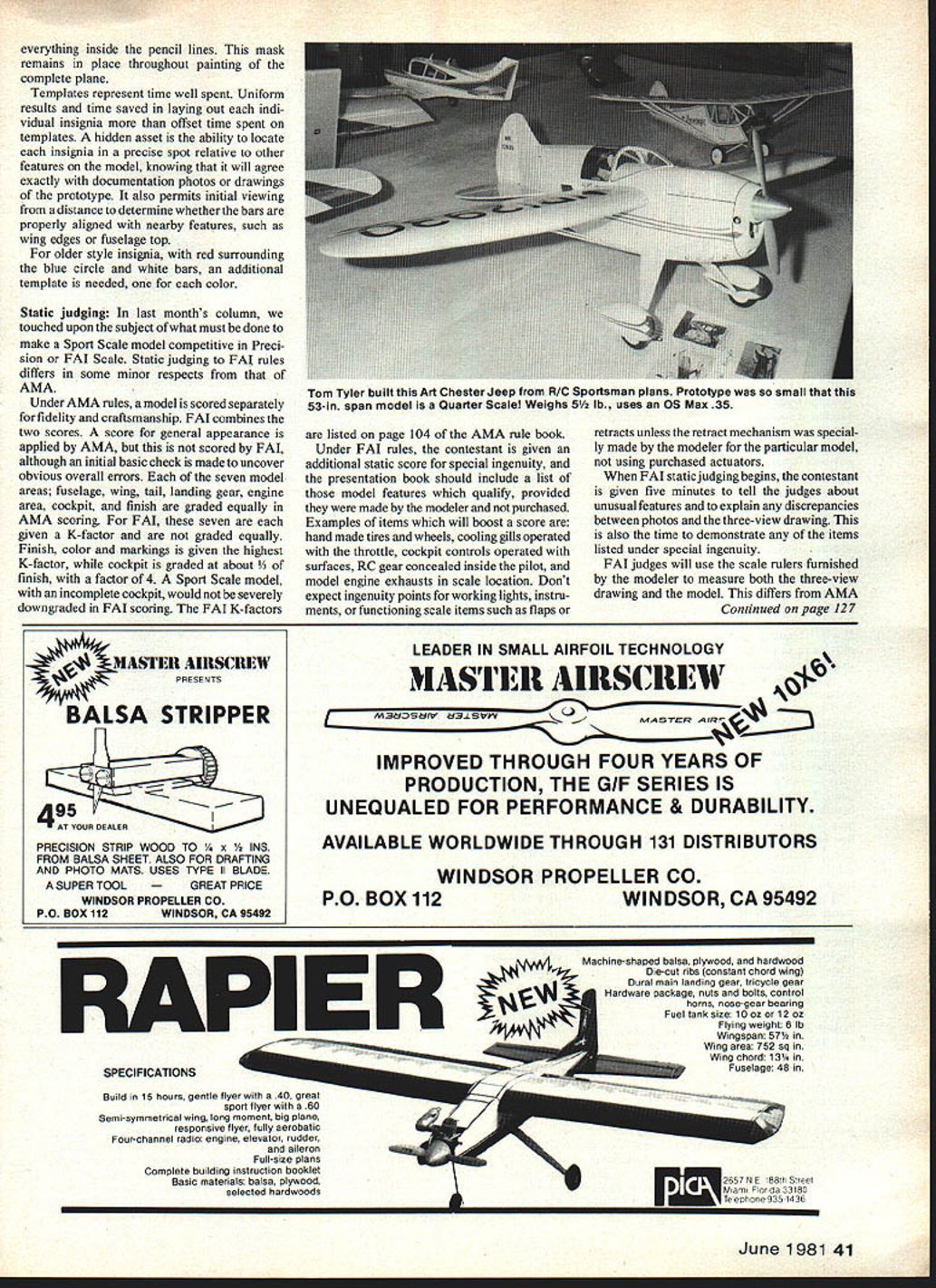
DIA. OF STAR POINTS
- For U.S. insignia the diameter of the star points is the basic dimension from which all other parts of the insignia are scaled. Use the diagram (or the formula) to relate bar length, bar width and blue field size to that diameter.
Steps for applying U.S. military insignia (summary)
- Make two full-size templates on heavy paper: star/bars and outer blue perimeter.
- Cut templates with X-Acto and straightedge.
- Spray a white base slightly larger than needed; let dry.
- Position star-and-bar stencil, trace lightly.
- Mask star and bars with fine-line plastic tape, cutting curves with a compass cutter on styrene if needed.
- Spray surrounding area with blue; remove inner mask.
- Center and tape outer perimeter template, trace inner edge, mask outside area.
- Spray final blue, remove masks when dry.
Static Judging
Precision FAI scale static judging under FAI rules differs in some respects from AMA. Under AMA rules, models are scored separately for fidelity and craftsmanship; FAI combines those into a single score. General appearance as applied by AMA is also scored by FAI, although FAI makes an initial basic check to uncover obvious overall errors.
Under AMA, seven model areas—fuselage, wing, tail, landing gear, engine area, cockpit and finish—are graded equally. FAI assigns different K-factors to those seven areas; finish, color and markings are given the highest K-factor, while cockpit is graded about K = 4. A Sport Scale model with an incomplete cockpit would be severely downgraded under FAI scoring. FAI K-factors are listed in the AMA rule book.
FAI also gives an additional static score for special ingenuity and presentation. The modeler should supply a list of model features that qualify, provided they are made by the modeler and not purchased. Examples of features that will boost a score:
- Hand-made tires and wheels
- Cooling gills operated with the throttle
- Cockpit controls operated with surfaces
- RC gear concealed inside the pilot figure
- Model engine exhausts in scale location
Do not expect ingenuity points for working lights, instruments, or functioning scale items such as flaps or retracts unless the retract mechanism or other functioning gear was specially made by the modeler for that particular model (not using purchased actuators).
When FAI static judging begins, the contestant is typically given five minutes to tell the judges about unusual features and to explain any discrepancies between photos and the three-view drawing. This is also the time to demonstrate items listed under special ingenuity. FAI judges will use the scale rulers furnished by the modeler to measure both the three-view drawing and the model—this differs from AMA practice.
FAI vs AMA (key points)
- FAI: combines fidelity and craftsmanship into one score; uses K-factors; emphasizes finish/color/markings.
- AMA: scores fidelity and craftsmanship separately; equal weighting of seven areas.
- FAI: awards special ingenuity points for modeler-made features; requires demonstration/time to explain.
- Provide documentary evidence (photos/three-views) and scale rulers when requested.
RC Scale — What Judges Examine
Judges check many specific items for scale fidelity and craftsmanship. Important areas and common judging concerns:
Fuselage and skinwork
- Metal-type aircraft: panel lines should be scribed with depth (not just painted on). Older planes should show overlapping joints oriented correctly to shed water; later aircraft have flush joints with scribed appearance.
- Rivets: correct size, location, type and quantity.
- Fabric covering: should reveal properly sized and located structure beneath; stringers and longerons should be narrow and rounded where they contact fabric, with tapes covering wrap points. Duplicate documented wrinkles or imperfections if present. Accuracy of length, width, cross section and feature locations is critical.
Wing and control surfaces
- Fabric-covered wings: rib tapes and stitching add authenticity but need not be obtrusive. Tape edges may almost vanish on a well-finished plane.
- Spars should not be visible through fabric. Oversize trailing edges reduce score.
- Wingspan, chord, airfoil thickness, dihedral angle, and dimensions/locations of ailerons and flaps are checked closely.
- Bolts for wing attachment should be recessed and covered unless visible on the original.
- Panel lines on metal wings must overlap in the direction of airflow.
- External pushrods and commercial clevises/horns not used on the original will cause downgrading.
- Altered wing or tail areas (e.g., widened tips to increase stability) are easily detected and penalized.
Landing gear, wheels and wells
- Shape, location and height must be correct; shortened legs for ground stability (common on Fw-190 models) are a noticeable fault.
- Tires: shape, diameter, thickness, tread pattern and sidewall markings are inspected.
- Retractable gear should move in a scale manner; gear doors should function in the correct sequence.
- Wheel wells should be painted and show interior detail, plumbing, hydraulic lines as appropriate.
- Tailwheel should swivel and be mounted in a scale manner.
Engine and cowling
- Cooling: hiding the model engine while keeping it sufficiently cooled is difficult. Some modelers expose part of the engine for cooling; others use elaborate ducting to fully hide it.
- Cowl shape, ventilation openings, louvers, hinges and latches must match the prototype.
- Visible dummy engine components should be accurately represented. Exhausts are best piped out at the true scale location.
- Scale propellers should match the prototype (see related column about propellers).
Cockpit and cabin
- In AMA judging the cockpit is weighted equally with other areas; in FAI it has a lower K-factor but is still important.
- Seats, controls and interior finish require effort independent of model size; instrument panels are easier on larger models.
- Most cockpit judging is by eye for proportion rather than rule measurements.
- Radio equipment should be well hidden; raising the cockpit or cabin floor to conceal servos is frowned upon.
Finish, color and markings
- Finish, color and markings are heavily weighted in Sport Scale and FAI. Getting markings correctly sized and placed is mechanical but accounts for many errors.
- Use photographs for final evidence whenever possible. Profile illustrations (artist renditions) are acceptable per the rules but may not show accurate detail or exact colors. Be prepared to justify color choices to the judges.
- Colors in photographs can change with storage and printing; judges expect reasonable justification. A scrap of original fabric may not reliably represent the original color if it has faded. Judges place weight on the modeler’s ability to present comparable references for color and finish.
Common faults and tips
- Avoid external model-type hardware not present on the prototype (clevises, horns, visible servos).
- Keep proportions correct rather than enlarging control surfaces or thickening tips for stability.
- Reproduce fabric texture and tape detail at scale—fine weave and roughness affect appearance.
- Provide good documentation (photos and three-view) and be ready to explain any unavoidable discrepancies.
- Additional static judging guidance appears under “Airrex” on pages 104–105 of the 1980–81 AMA rule book.
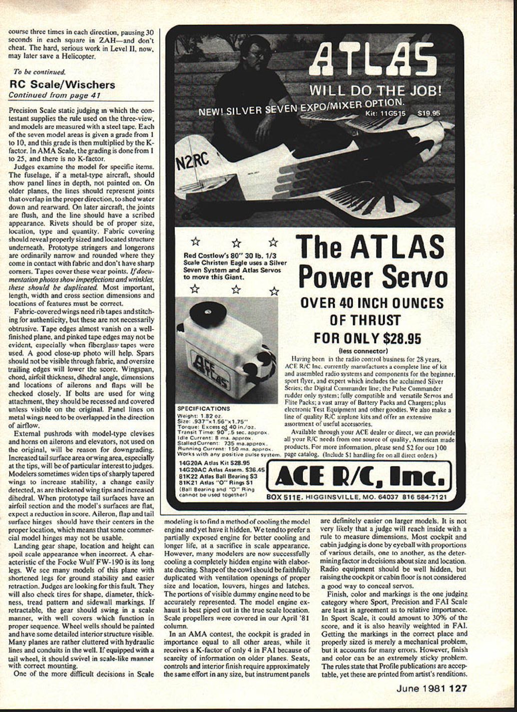
Wischers' Example — Douglas A-20G
Wischers’ newest Douglas A-20G WWII attack bomber:
- Wingspan: 77 in
- Weight: 125 lb
- Construction: surfaces covered with fiberglass cloth and K&B resin
- Paint: model-railroad Floquil for minimum weight and good coverage
Bob used paper templates to outline masking areas for the A-20’s wing insignia. This simplified procedure produced uniform emblems on the model and saved time laying out individual insignia. Templates also allow precise placement relative to other model features and documentation photos. Older-style insignia with a red surrounding circle require an additional template for the red color.
Color Documentation and Proof
Be cautious using artist paintings or profile art for color authentication; these may be rejected since they are artist renditions and not always accurate. Color photographs are acceptable, but remember that colors can begin changing as soon as photos are printed. A piece of original fabric offered as proof must be justified—fabric fades and the original plane may have changed hue over time. Ultimately, the modeler should provide references that allow judges to compare and evaluate color, texture and finish. Be prepared to justify choices.
To be continued.
Bob and Dolly Wischer Rt. 1, S-221 Lapham Peak Road Delafield, WI 53018
Transcribed from original scans by AI. Minor OCR errors may remain.

