
Radio Control: Scale
Bob & Dolly Wischer
Trade-offs
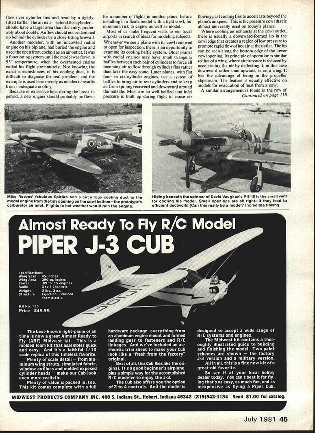
How much should the Scale modeler be willing to pay for true-scale appearance? Sacrificing engine life and performance to garner extra static points is often considered a satisfactory trade-off when the engine must be buried in the nose of a model that has no openings for cooling. This is partially understandable when the model is to have only a few flights in contests which are sufficiently important to the modeler to warrant risk of permanent damage to the engine. It is part of the win-at-all-costs technique. Rather than make non-scale cooling openings in the nose, or leave portions of the engine exposed to view, the modeler elects to take a chance on damaging his engine, particularly if it must be flown in hot weather. Most probable candidates for this treatment, that we have seen, were in the Precision Scale class, with a few in Sport Scale.
It is an odd fact that some of the most attractive prototypes have completely cowled engines. Best examples are the ever-popular WWII fighters with liquid-cooled engines. We have also seen models of radial-engine prototypes with the model engine completely concealed.
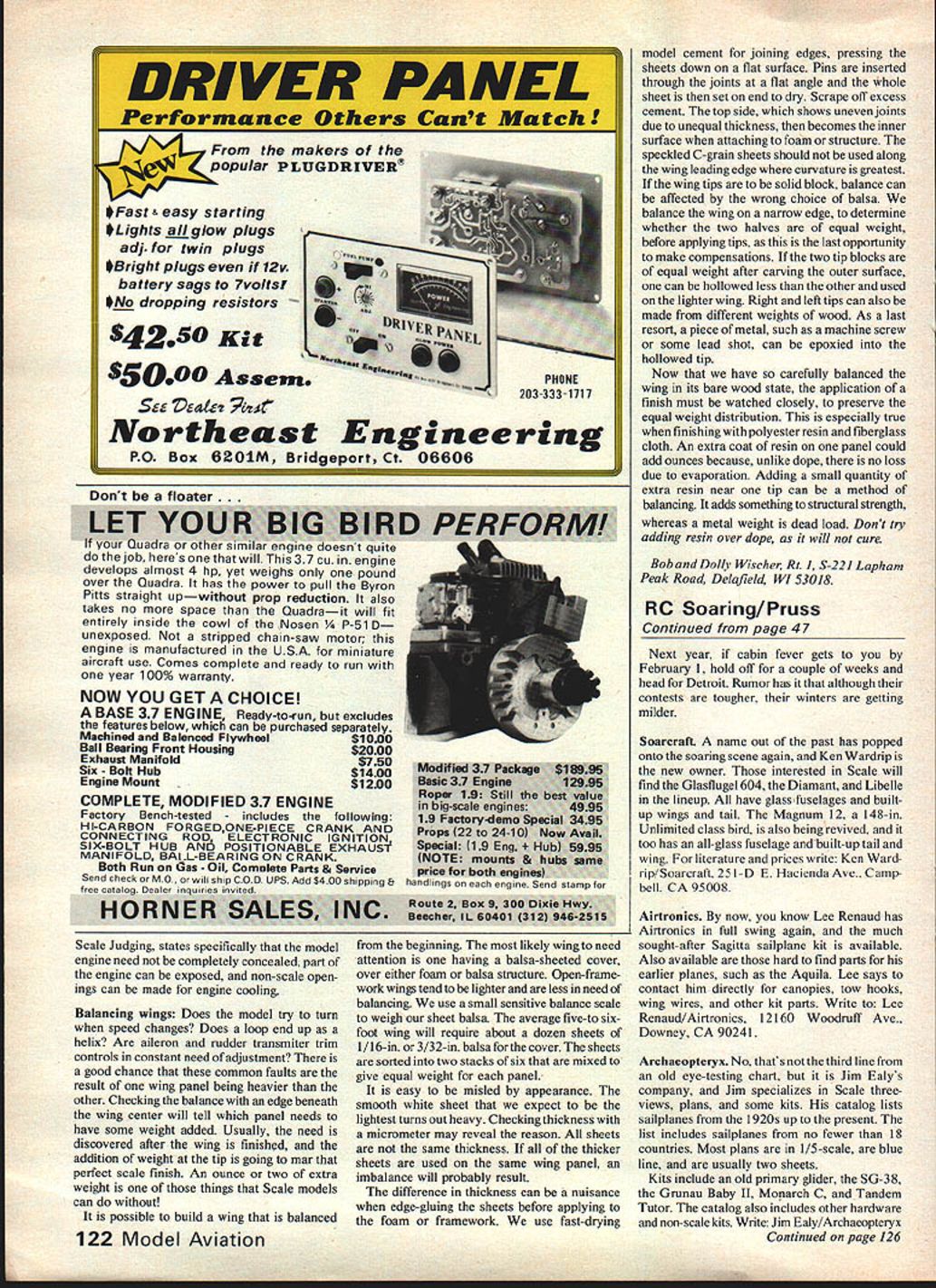
The Spitfire flown by Mike Reeves in last year's World Championship is a specific example of cooling problems. At home in England, where hot weather is not often encountered, Mike wasn't too concerned about cooling. Fortunately, the expected heat at Ottawa didn't occur, and his cooling method proved adequate. His Spitfire had a small scoop at the cowl bottom, which is the carburetor air inlet in the prototype. A duct carried air forward from this scoop. By using baffles to direct all incoming air over the engine's cooling fins, Mike had managed to get the necessary three flights without engine failure. The same system being used in the heat of an American summer would be marginal in cooling capacity.
A large quantity of air isn't required if it is used conservatively and not allowed to spill through the cowl unhindered. Control Line Speed fliers and Pylon Racers have demonstrated the use of directed air for cooling, but it must be kept in mind that their speeds are higher and airflow is greater than we usually have in Scale.
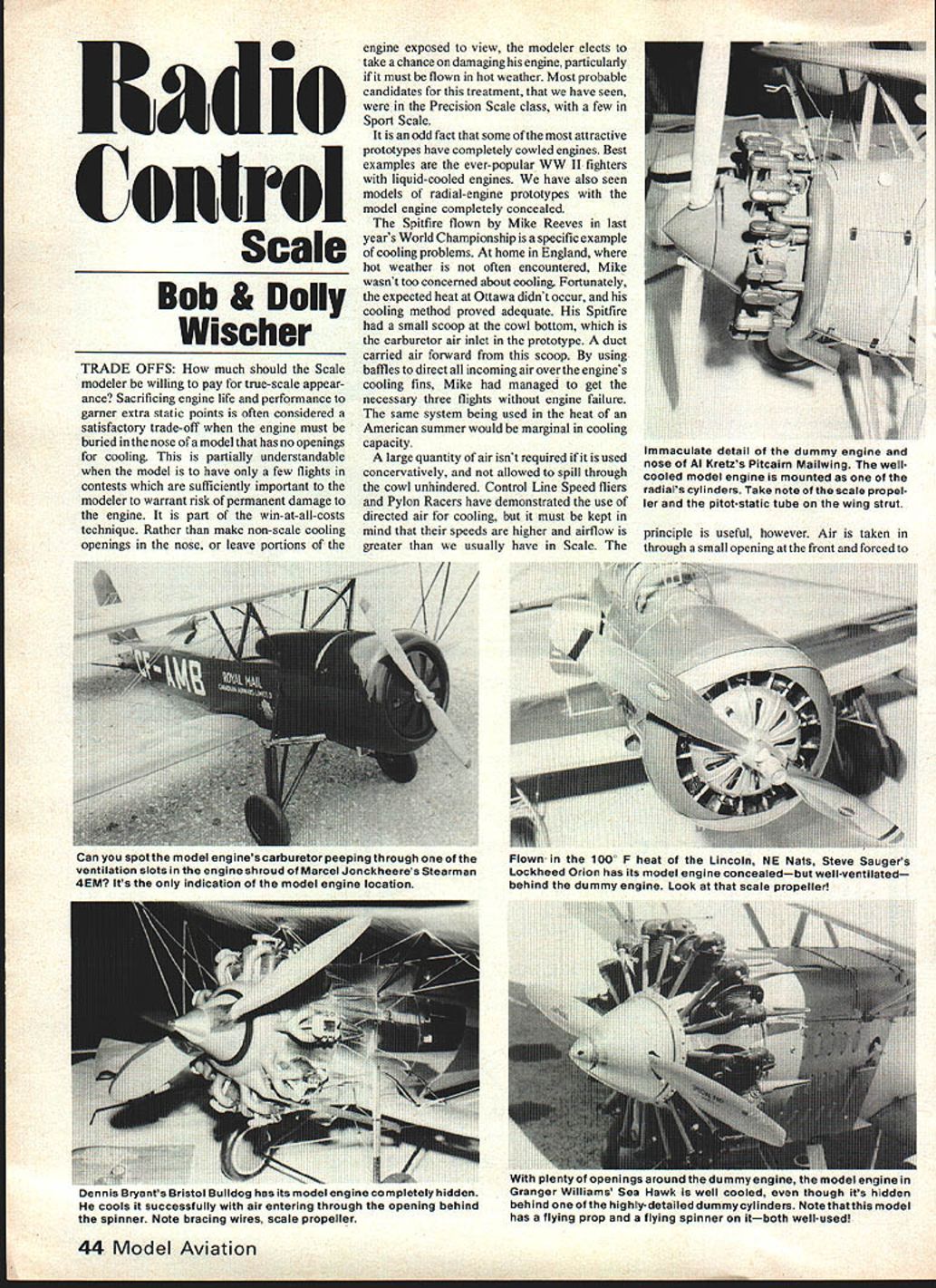
The principle is useful, however. Air is taken in through a small opening at the front and forced to flow over the cylinder fins. The head should have a tightly fitted baffle. The air exit behind the cylinder should have a larger area than the entry—preferably about double. Airflow should be dammed up behind the cylinder by a close-fitting firewall.
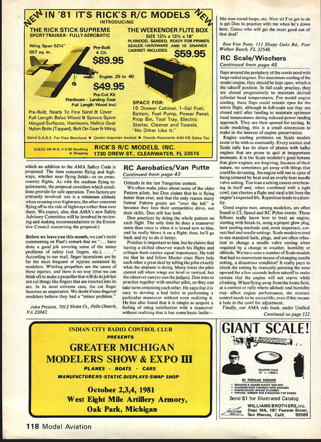
Another modeler uncowled a radial-engine biplane that had its engine buried; the open-front cockpit was used as the air outlet and the system functioned until the model was flown in 95°F temperature. The engine overheated and the flight ended prematurely. Without knowing the exact circumstances of the cooling duct, it is difficult to diagnose the real problem; the example merely demonstrates the results of inadequate cooling.
Because of the possibility of excessive heat during the break-in period, a new engine should probably be flown a number of times in another plane before installing it in a Scale model with a tight cowl—minimum risk to the engine in the well-cowled model.
Most of us make frequent visits to local airports to search for ideas and modeling subjects. Whenever we see a plane with its cowl removed, it's an open inspection opportunity to examine its cooling baffle system. Older planes with radial engines may have small triangular baffles between pairs of cylinders to force incoming air to flow through the cylinder fins rather than take the easy route. Later planes with flat four- and six-cylinder engines use a system of baffles to bring air to the rear cylinders and keep air from spilling rearward and downward around the outside.
On many well-baffled inlets, pressure built up during flight causes the air flowing past the cooling fins to accelerate beyond the plane's airspeed. A pressure cowl is almost universally used on today's planes. Cooling air exhausts through a cowl outlet usually formed with a downward lip; the cowl edge creates a region of low pressure to promote rapid flow of hot air at the outlet. The lip can be seen along the bottom edge of the lower cowl opening. Its principle of operation is similar to that of a wing, where air pressure is reduced by accelerating the air by deflecting it—in this case downward rather than upward, as on a wing. It has the advantage of being in the propeller slipstream. The feature is equally effective on models for evacuation of heat from a cowl.
A similar arrangement is found in the row of flaps around the periphery of the cowls used with large radial engines. For maximum cooling of the model engine, they should be kept open, which is the takeoff position. In full-scale practice, they are closed progressively to maintain desired cylinder head temperatures. For model engine cooling, these flaps could remain open for the entire flight, although in full-scale use they are closed until after landing to maintain optimum head temperatures during reduced-power landing approach. They are then opened for taxiing. In scale modeling, this is a small concession to make in the interest of engine preservation.
Engine cooling problems on Scale models seem to be with us constantly. Every contest and Scale rally has its share of planes with balky engines that are prone to quit at inopportune moments. It is the Scale modeler's good fortune that glow engines are forgiving; because of their nature, we sometimes get away with things that could be devastating. An engine will run in spite of being tortured by heat and an overly-lean needle valve setting. Too lean a setting causes overheating in itself and, when combined with a tight cowl, can shorten a flight and steal a bit from the engine's expected life. Repetition leads to calamity.
Good engine men, among modelers, are often found in CL Speed and RC Pylon events. These fellows really know how to treat an engine, starting with break-in, using a proper glow plug, best cooling methods and, most important, correct fuel and needle settings. Scale modelers tend to use standard fuels and plugs, and are often reluctant to change a needle valve setting when required by a change in weather, humidity or altitude. We have seen a number of Scale models that had no convenient means of changing needle setting, a disastrous condition! It really pays to be able to make a needle change by manually pointing the nose up or down for a few seconds before takeoff to make certain that the engine will not starve while climbing. When flying away from the home field, at a contest or rally where altitude and humidity may affect engine performance, the mixture control needs to be accessible, even if this means a hole in the cowl for adjustment.
Finally, our AMA rule book, under Unified Scale Judging, states specifically that the model engine need not be completely concealed; part of the engine can be exposed, and non-scale openings can be made for engine cooling.
Balancing wings
Does the model try to turn when speed changes? Does a loop end up as a helix? Are aileron and rudder transmitter trim controls in constant need of adjustment? There is a good chance that these common faults are the result of one wing panel being heavier than the other. Checking the balance with a knife blade beneath the wing center will tell which panel needs to have some weight added. Usually, the need is discovered after the wing is finished, and the addition of weight at the tip is going to mar that perfect scale finish. An ounce or two of extra weight is one of those things that Scale models can do without.
It is possible to build a wing that is balanced from the beginning. The most likely wing to need attention is the one having a balsa-sheathed cover, over either foam or balsa structure. Open-frame work wings tend to be lighter and are less in need of balancing. We use a small sensitive balance scale to weigh our sheet panels. The average five- to six-foot wing will require about a dozen sheets of 1/16-in. or 3/32-in. balsa for the cover. The sheets are sorted into two stacks of six that are mixed to give equal weight for each panel.
It is easy to be misled by appearance. The smooth white sheet that we expect to be the lightest turns out heavy. Checking thickness with a micrometer may reveal the reason. All sheets are not the same thickness. If all of the thicker sheets are used on the same wing panel, an imbalance will probably result.
The difference in thicknesses can be a nuisance when edge-gluing the sheets before applying to the foam or framework. We use fast-drying model cement for joining edges, pressing the sheets down on a flat surface. Pins are inserted through the joints at a flat angle and the whole sheet is then set on end to dry. Scrape off excess cement. The top side, which shows uneven joints due to unequal thickness, then becomes the inner surface when attaching to foam or structure. The speckled C-grain sheets should not be used along the wing leading edge where curvature is greatest.
If the wing tips are to be solid block, balance can be affected by the wrong choice of balsa. We balance the wing on a narrow edge, to determine whether the two halves are of equal weight, before applying tips, as this is the last opportunity to make compensations. If the two tip blocks are of equal weight after carving the outer surface, one can be hollowed less than the other and used on the lighter wing. Right and left tips can also be made from different weights of wood. As a last resort, a piece of metal, such as a machine screw or some lead shot, can be epoxied into the hollowed tip.
Now that we have so carefully balanced the wing in its bare wood state, the application of a finish must be watched closely to preserve the equal weight distribution. This is especially true when finishing with polyester resin and fiberglass cloth. An extra coat of resin on one panel could add ounces because, unlike dope, there is no loss due to evaporation. Adding a small quantity of extra resin near one tip can be a method of balancing. It adds something to structural strength, whereas a metal weight is dead load. Don't try adding resin over dope, as it will not cure.
Bob and Dolly Wischer, Rt. 1, S-221 Lapham Peak Road, Delafield, WI 53018.
Transcribed from original scans by AI. Minor OCR errors may remain.

