
Radio Control: Scale
Bob & Dolly Wischer
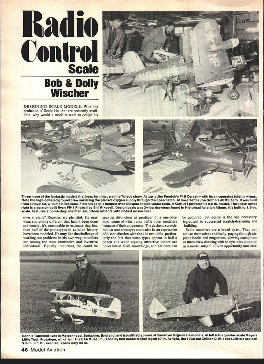
Designing Scale Models
With the profusion of scale kits presently available, why design your own airplane? Reasons are plentiful:
- You may want something different that hasn't been done previously — less than half of the prototypes in aviation history have been modeled.
- You may enjoy the challenge of working out problems your own way; modelers are inventive and innovative.
- You may seek distinction as the producer of a one-of-a-kind, perhaps baffling other modelers by the uniqueness.
- You may be dissatisfied with available kits — some types appear in many kits while equally attractive planes are never kitted.
Desire is the necessary ingredient for successful scratch-designing and building. Skill, knowledge and patience can be acquired.
Documentation and research
Scale modelers save and file aviation books, magazines and three-view drawings, and keep a list of external information sources. For accurate work:
- Have more than one drawing for comparison.
- Don’t assume a three-view is correct — use photographs for verification.
- Gather all necessary documentation before starting design.
Choosing scale and the multiplication factor
Designing starts by determining the desired model size. Use a scale ratio rather than “inches-to-the-foot.” Examples: 4:1, 6.5:1, 8:1. Measure in decimal inches (U.S. industry standard) to be calculator-compatible.
Determine the multiplication factor to convert three-view dimensions to model size:
- Multiply or divide as follows: factor = model wingspan ÷ three-view wingspan.
- Enter that factor as a constant in your calculator and keep a written record; you will use it often.
On separate sheets (one per possible scale ratio) list the model’s critical dimensions:
- Multiplication factor
- Scale ratio
- Wingspan
- Chord
- Overall length
- Cowl diameter
- Fuselage width
- Wheel diameter
- Landing-gear tread width
- Wing area (rough estimate)
- Rough estimate of weight
Compare four or five scale-ratio sheets laid side by side to reveal limiting features:
- Wing area too small to carry estimated weight
- Wingspan too large to fit in a car
- Cowl too small to contain engine/muffler or too large for available propellers
- Wheel diameter incompatible with chosen engine
- Need for shaft extension or engine relocation
If necessary, shift the scale ratio slightly to accommodate an unwieldy feature.
Calculator and drawing surface
A simple four-function calculator with a CONSTANT key is sufficient and worth owning.
For drawing surfaces:
- A large flat board is useful — examples: half of a ping-pong top (4.5 × 5 ft) or a hollow-core door (30 × 80 in).
- Drawings can be made on inexpensive white shelf paper (48 in. wide) or tracing vellum (preferred for erasures).
- A 5-ft T-square reaches the full width; edges must be straight.
- Essential tools:
- Large plastic triangles
- Compass
- Several long ship curves and shorter French curves
- Large plastic protractor
- 12-in. decimal-inch scale graduated in 0.02‑in. increments (avoids fraction-to-decimal conversion errors)
Creating the enlarged drawing
Start with a basic reference line (engine thrust line, fuselage centerline, fuselage top). Using the multiplication factor:
- Take dimensions from the three-view through the calculator.
- Transfer points to the enlarged drawing.
- On the three-view, draw a few reference lines at right angles to the centerline if needed.
- From a front fuselage point, measure back to vertical lines and to wing leading/trailing edges, stabilizer edges and tail post. Plot these along the reference line on the large drawing.
- Measure from the reference line to the fuselage outline to plot the shape.
- Use the same method for wing and tail outlines and fuselage cross-sections.
Establish wing and tail incidence angles at this stage. Inexperienced designers should consult kit or magazine drawings for data on incidence and related critical dimensions.
Decide internal component locations early:
- Fuel tank, servos, receiver and battery pack.
- The battery is often the easiest way to adjust balance — consider alternate locations.
For wing drawing, choose a straight reference line (leading edge or spar centerline). The hinge line is a handy datum for tail surfaces. The mathematical method of enlarging with a calculator produces few errors and is relatively quick.
Drawing curved lines — the coordinate method
Curved outlines can be reproduced accurately as follows:
- On the three-view, draw a series of lines perpendicular to the basic reference line so they intersect the curve.
- Transfer the spacing of those perpendiculars to the large drawing.
- Measure the distance from the basic line to the curve at each point; transfer those measurements as dots on the perpendiculars.
- Connect the dots with a ship curve or French curve.
Note: most prototypes have few true curved lines; many outlines are straight segments joined by gentle curves. Tail surfaces and some elliptical wings are exceptions.
Design fidelity versus flightability
There is a temptation to alter shapes for better flying (increase wing area, widen fuselage, enlarge stabilizers). The Wischers have found this unnecessary:
- Maintain true scale outlines where possible; models that keep scale proportions fly in a scale-like manner.
- If wing area is inadequate, choose a slightly lower scale ratio to add area rather than changing the shape.
- Avoid widening fuselages or other changes that make the model look “like a model” rather than the real thing.
Construction details
Actual construction depends on the builder’s experience and innovation. When in doubt, copy successful ideas from other designers, kit plans and magazine drawings.
High-stress areas
Focus attention on high-stress points: engine mount/firewall, landing gear mount, and wing mounting.
Engine firewall and mount:
- A metal engine mount fastened to a plywood firewall is standard.
- Epoxy the plywood firmly to the fuselage structure and use triangular balsa gussets.
- For a .60-size engine: use 1/4‑in. plywood, or laminate two 1/8‑in. five-ply sheets with white glue. Press between boards with C-clamps until set, then cut the firewall from the laminated stock.
- For a wide fuselage, laminate three layers.
- For .40-size engines, use two or three layers of 3/32‑in. ply.
Landing gear:
- Music‑wire gear should be fastened with steel straps and machine screws to a plywood mount.
- Tie the plywood into the fuselage or wing with gussets and epoxy.
Wing mounting:
- Broaden contact area between wing and fuselage with doublers.
- Drill hardwood blocks in the wing for steel machine screws that thread into blind nuts in plywood plates attached securely to the fuselage.
Avoid overbuilding
It’s possible to add too much strength, which increases weight unnecessarily:
- The goal is to protect against internal damage from occasional hard landings, not to make the plane crash-proof.
- Overbuilt joints may survive a crash while the rest of the aircraft is destroyed — wasted weight.
- Use heavy ply and hard balsa only where required. Excessive reinforcement can double weight and worsen flight characteristics.
General construction advice
- Borrow good ideas from other designers; few solutions are wholly original.
- Limit the number of scratch-built models you attempt — availability of good three-views and proximity to the prototype (museum or airport access) will restrict choices.
- Keep track of sources for drawings and photos; thorough documentation is invaluable.
Final notes
Designing your own scale model is rewarding: it produces unique subjects, hones problem-solving skills, and can result in accurate, scale-like flight without sacrificing appearance. Use decimal-inch measurement and a constant multiplication factor for reliable enlargements, plan component locations early, protect high-stress areas appropriately, and avoid unnecessary overbuilding.
Bob and Dolly Wischer Rt. 1, S-22 Lapham Peak Road, Delafield, WI 53018.
Transcribed from original scans by AI. Minor OCR errors may remain.

