
Radio Control: Scale
Bob & Dolly Wischer
Needle Valves
Most of us in Scale modeling have a common problem — adjusting the needle valve of a completely cowled engine without making a hole in the cowl. Older models often have an unsightly hole, but recently several methods for indirect adjustment have become popular.
The quickest and simplest method is a flexible shaft soldered directly to the needle and extending out the air exit at the cowl’s aft end (assuming such an opening exists). This works well if the cowl is sufficiently wide to permit a reasonably large radius bend in the shaft. A sharp bend hampers fine adjustments because the shaft tends to twitch from spring action and friction.
- Shaft material: 0.050-in. dia. steel multi-strand cable enclosed in a nylon tube (intended for throttle or nose-wheel hookup).
- For smooth operation, anchor the tube at both ends. Make an aluminum or brass bracket that fastens to an engine-mount bolt to hold the flexible shaft in alignment with the needle valve.
- Use a short brass tube coupling soldered between shaft and needle. The needle will probably need to be shortened and reduced in diameter to accept the brass tube; this can be done with a file or by turning the needle shank in an electric drill, being careful not to distort the threads.
- A knurled nut from a battery terminal (like the big 1-1/2 V ones once used to heat glow plugs) makes a good finger grip when soldered to the flexible shaft and positioned just inside the cowl opening where it is not easily seen.
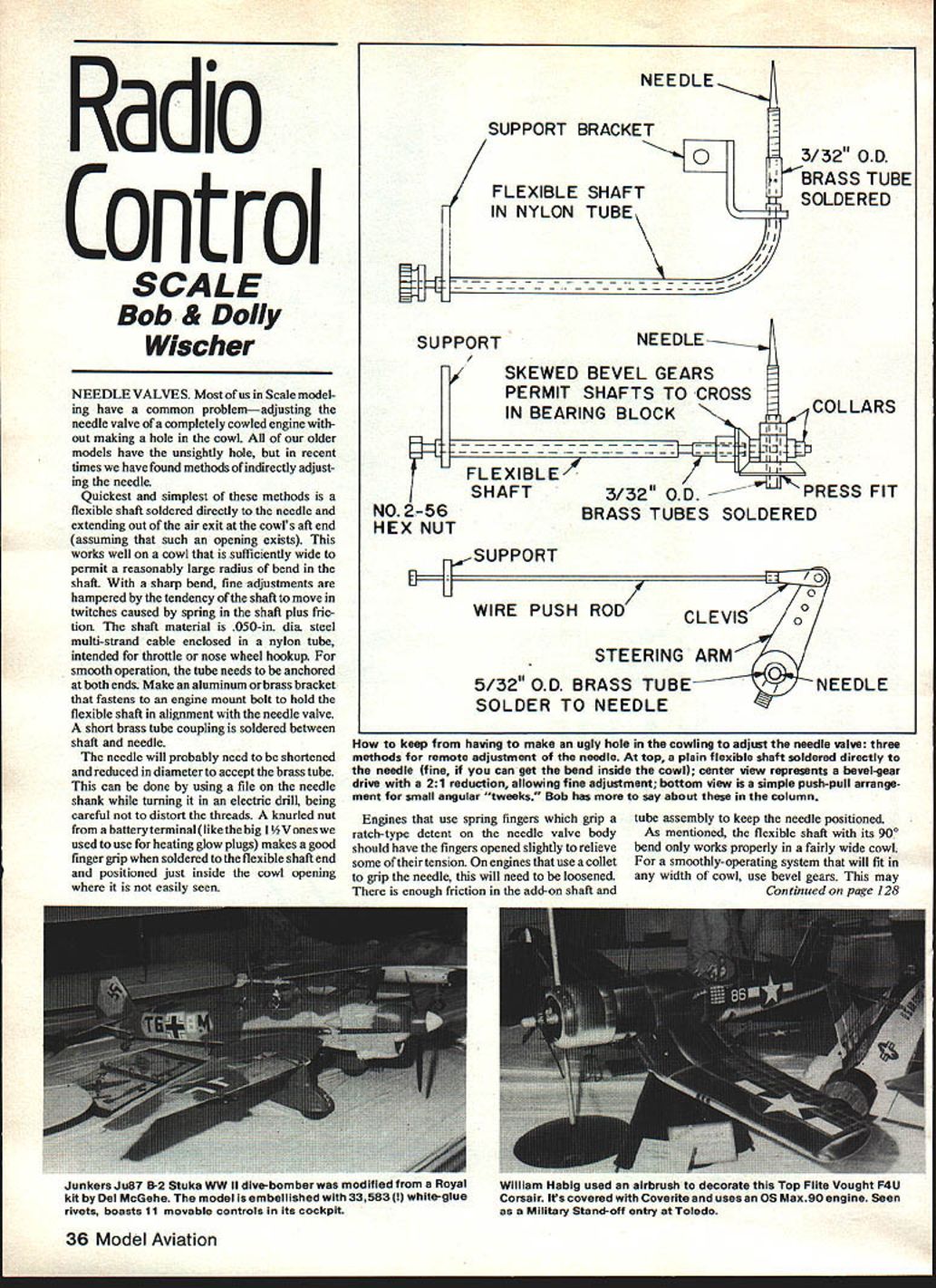
Three basic arrangements are commonly used for remote needle adjustment:
- Flexible shaft soldered directly to the needle — fine if you can get the bend inside the cowl.
- Bevel-gear drive with a 2:1 reduction — allows finer adjustment.
- Simple push-pull arrangement — provides small angular tweaks.
A few cautions:
- Engines that use spring fingers to grip a ratchet-type detent on the needle valve body should have the fingers opened slightly to relieve some tension.
- Engines that use a collet to grip the needle will need the collet loosened. There is generally enough friction in the add-on shaft and tube assembly to keep the needle positioned.
- The flexible shaft with a 90° bend only works properly in a fairly wide cowl. For a smoothly operating system that will fit any cowl width, consider bevel gears.
Bevel-gear solution (compact and simple)
- The model-railroad industry supplies tiny gears in various sizes and ratios. Precision Scale Co. offers molded plastic gearboxes with 1:1 helical gears or 1:1 in-line bevel gears that can be mounted directly to the needle and require no other support. Skewed bevel gears are available in 1:1 or 2:1 ratios.
- These tiny gears (less than 1/8-in. diameter) are kept in alignment by a molded cross fitted to the needle. A flexible shaft extension is soldered to a short length of 3/32-in. O.D. brass tube which is pressed into the hub of the driving gear. A nylon tube guides the shaft to the rear of the engine cowl where the tube is supported by an aluminum bracket.
- Solder a 2-56 nut on the shaft end and use a 1/16-in. nut driver to adjust the needle valve. The nut driver readily engages the nut while the engine is running, and the nut can be hidden within the cowl rear opening.
- The needle will probably require some dressing down in diameter so a 3/32-in. O.D. brass tube can be soldered over it. The bevel gear then press-fits over the tube. Bevel gear sets come complete with the necessary bushings for assembly.
Push-pull arrangement (limited but often sufficient)
- Many scale modelers only need occasional tweaks rather than wide rotational travel. Some engines (the H.P. type comes to mind) have a large-diameter knurled barrel pressed onto the needle with a pair of flat springs providing detent tension.
- A nylon steering arm with a set screw (intended for a nosewheel) can be clamped to the barrel. Extend a pushrod and clevis from the arm to the rear of the cowl where the rod can be reached with needle-nose pliers. The push-pull action can provide about 90° of needle rotation, which is often enough.
- Du-Bro steering arms include a handy swivel to clamp the pushrod. Solder a couple of telescoped brass tube bushings to a plain straight needle to bring it up to 5/32-in. diameter so a steering arm fits snugly.
Why worry about needle valve setting?
- Scale model engines are often fully cowled and hidden behind dummy engines, and they can overheat. Running slightly lean worsens overheating and can cause lubricant breakdown, piston/cylinder distortion, and eventual seizure.
- As drag from the propeller diminishes in flight, engine speed increases and more fuel is needed. As fuel level in the tank decreases during flight, the mixture tends to lean out. A nose-high attitude, tanks placed too far rearward or too low, and reduced tank pressure can all reduce fuel flow.
- Mufflers mask engine sound, so a lean run may not be detected immediately. Setting the needle slightly rich before takeoff is a good practice — but only if the needle is easily adjustable.
- Congealed castor or other residues can partially plug fuel passages, necessitating needle readjustment.
Muffler pressure and tank sealing
- Manufacturers recommend muffler pressure to ensure constant fuel flow. If a needle setting suddenly changes, check for leaks in the tank or plumbing that prevent tank pressure from building.
- For muffler pressure to work, the system must be sealed, including the tank fill tube. Use a 6-32 machine screw to plug the open end of the tube. Cut the fuel tube end square so the screw head seals against the tube underside; otherwise a leak could form along the threads. Repeated insertion of a screw can crack the tube and cause pressure loss.
Cooling considerations
- Fuel provides some cooling (evaporation of alcohol), so starving an engine compounds overheating. The lean mixture burns hotter and there is less fuel to cool the engine.
- Internal cowl baffles that force incoming air through the cylinder fins are a necessity. If space allows, a large heat sink fastened to the cylinder head (as used on helicopters or race cars) is an alternate solution.
Scale publication
For the third time in as many years, the British magazine Radio Control Models and Electronics has produced another RC Scale Aircraft Special. These books contain a wealth of ideas for Scale modelers on all aspects of the hobby.
- Color: Emphasis on military aircraft, with a comprehensive listing of color reference sources in the U.K. and the U.S.A., including addresses.
- Construction techniques: Descriptions by prominent British scale modelers with detailed information on building methods and producing the items needed for a top-quality model, starting from documentation, photos, and prototype measurements.
- Metal parts: Australian Ross Woodcock describes producing metal parts using lithographic aluminum sheet, including punching, forming, and annealing to allow deep draws without fracturing.
- Strength and materials: Eric Coates outlines methods of building-in strength through construction techniques and proper use of materials, particularly struts and wire bracing for multi-wing airplanes. He developed a system for forming flat flying wires from music wire for absolute straightness and realistic appearance.
- Other sections: Multi-engine airplanes, wood bending and laminating, joining and finishing metals, landing gear construction, wing slots, and coupled ailerons and rudder.
- Plans: The book contains full-size plans for a 1/8-scale Fokker Eindecker.
Price: $3.00. Order direct from Model and Allied Publications, P.O. Box 35, Bridge Street, Hemel Hempstead, Herts., HP1 1EE, England.
Bob and Dolly Wischer Rt. 1, S-221 Lapham Peak Rd., Delafield, WI 53018
Transcribed from original scans by AI. Minor OCR errors may remain.

