
Radio Control: Scale
Bob & Dolly Wischer
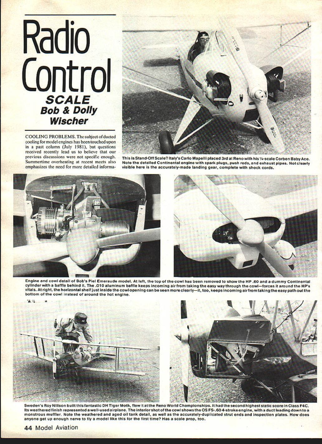
Cooling Problems
The subject of ducted cooling for model engines was touched on in a past column (July 1981), but recent questions and summertime overheating at meets show that more specific information is needed.
Cowled Engine with Dummy Radial
Cooling a cowled engine mounted behind a dummy radial is relatively simple. Dummy half-cylinders are mounted on a 1/16" plywood disc that completely fills the opening in the cowl front. The model engine is positioned so its cylinder centerline falls between two dummy cylinders. For most installations this will be at an angle to the left (viewed from the front) so that engine exhaust will be downward. This angle facilitates mounting the muffler near the cowl bottom and helps lower the needle valve relative to the fuel tank centerline.
For a nine-cylinder dummy radial, the preferred position is about 140° between cylinders 4 and 5, counterclockwise from the top. This places the model engine side-mounted with its cylinder 50° below horizontal (or 10° below if the model engine is placed between cylinders 3 and 4).
The plywood disc is then cut away between cylinders 4 and 5 so trapped air can flow rearward. This opening will permit sufficient airflow to cool a .60 or .90 engine.
Airflow Baffles and Plates
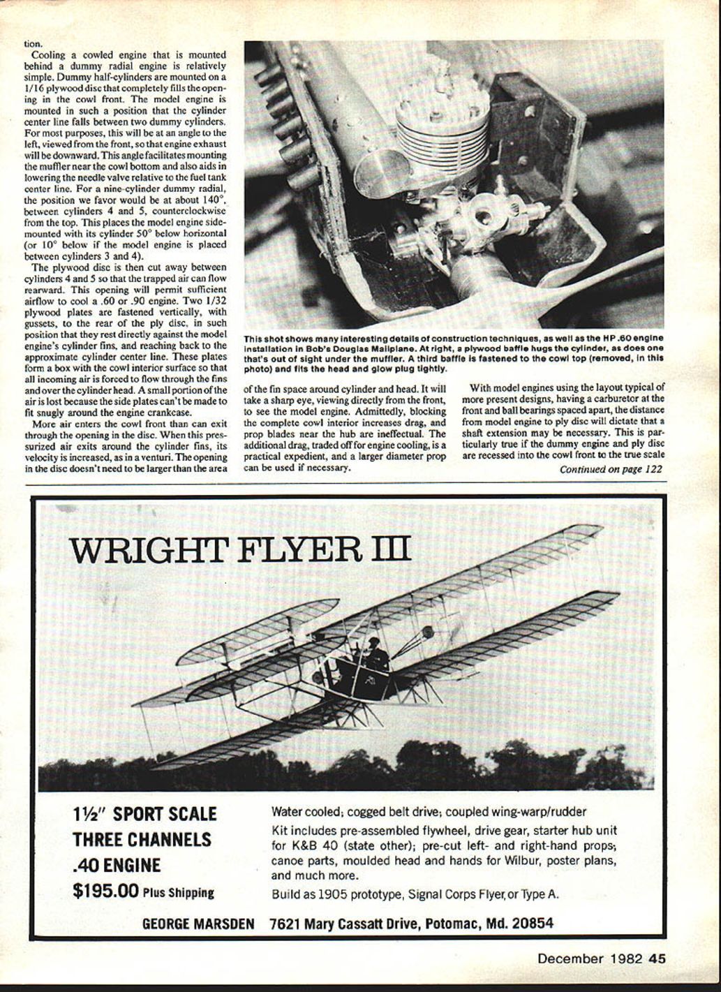
Two 1/32" plywood plates are fastened vertically, with gussets, to the rear of the plywood disc so they rest directly against the model engine’s cylinder fins and reach back to approximately the cylinder centerline. These plates form a box with the cowl interior so that all incoming air is forced through the fins and over the cylinder head. A small portion of the air is lost because the side plates can’t be made to fit snugly around the engine crankcase.
More air enters the cowl front than can exit through the opening in the disc. When this pressurized air exits around the cylinder fins, its velocity is increased, as in a venturi. The opening in the disc doesn’t need to be larger than the area of the fin space around the cylinder and head. It will take a sharp eye, viewing directly from the front, to see the model engine.
Blocking the complete cowl interior increases drag and makes prop blades near the hub ineffectual. The additional drag is a practical tradeoff for engine cooling, and a larger diameter prop can be used if necessary.
Shaft Extensions and Propellers
With modern model engines that have front-mounted carburetors and widely spaced ball bearings, the distance from the model engine to the plywood disc may require a shaft extension. This is especially true if the dummy engine and plywood disc are recessed into the cowl front for scale appearance.
Some modelers mount dummy engines close to the cowl front to avoid a shaft extension, but this adversely affects scale appearance. Decide early in construction whether to use a shaft extension, since using one means all flying propellers must be drilled out to accept the larger-diameter prop nut/sleeve used with the extension. Shaft extensions of various diameters and lengths are available from Fox Manufacturing Co.
Fastening the plywood disc and dummy engine into the cowl is one of the last assembly steps. Most cowls taper toward the front, and the disc diameter will vary depending on its fore-and-aft position, so the shaft-extension decision should be made early.
Flat Engines and Cowl Shelves
Aircraft with flat four- and six-cylinder engines usually have one large or two small ventilation openings in the cowl front. Models of these planes typically use a side-mounted engine that places the cylinder behind the opening on the left side. If nothing is done, incoming air will take the easy route through the open right side and cooling of the cylinder will suffer.
To prevent this, block the right opening with an aluminum or plywood plate at a point where it will rest against the engine crankcase. Cover this plate later with a dummy cylinder to simulate a Lycoming or Continental engine. Air entering the right side is then diverted over to the left.
Full-size aircraft with this cowl type have a shelf just inside the opening, extending full width, that fills the space between the opening's lower edge and the engine. This forces incoming air upward and rearward to cool the rear cylinders. On models, the shelf is also necessary to block air exit downward. The shelf extends rearward until it contacts the cylinder. A litho-plate aluminum shelf is supported by a plywood former cemented into the cowl bottom. If there is a gap between the cylinder and the inner surface of the cowl at the top, fill it with a litho-plate or plywood baffle placed close to the fins. This ensures incoming air is forced over the cylinder and head. Some air will spill through gaps around the crankcase, but that loss also provides crankcase cooling.
Cowl Exits and Cooling Gills
Heated air expands and requires an exit somewhat larger than the disc or cowl opening. You can accelerate air out of the exit with features such as controllable cooling gills. Many WW II radial-engined planes had such gills; they are useful on models too. Model gills can't be closed after takeoff like on full-scale aircraft, but they can be partially closed in flight if a modeler devises a mechanism.
Bob Karlsson uses spring-loaded cooling gills on his Wildcat that are actuated by the slipstream. At slow speed, they are held open by a spring. Gills are effective because they protrude into the slipstream and create a low-pressure region behind them that pulls air forcefully out of the cowl. A slight downward-formed edge at the exhaust air opening on light planes serves the same purpose. With such a feature to accelerate outgoing air, a smaller cowl opening can be used, equivalent to that of a larger exit.
Liquid-Cooled Engines and Radiator Ducting
Models of prototypes with liquid-cooled engines are the most difficult to cool without introducing visible non-scale openings. Antiques with large front radiators pose no problem; the difficulty lies with WW II types that had remote radiators under the wing or belly.
Examples from published sources:
- George Rose's Curtiss Hawk P-6E uses a small plate that folds down to admit incoming air at the cowl front. The plate remains part of the model whether it is down or up, which avoids violating contest rules about adding or removing parts after static judging.
- Mick Reeves' Spitfire ducts air from a small scoop in the lower cowl surface.
Neither example has a large opening, so the air must be used frugally by installing baffles around the cylinder and head.
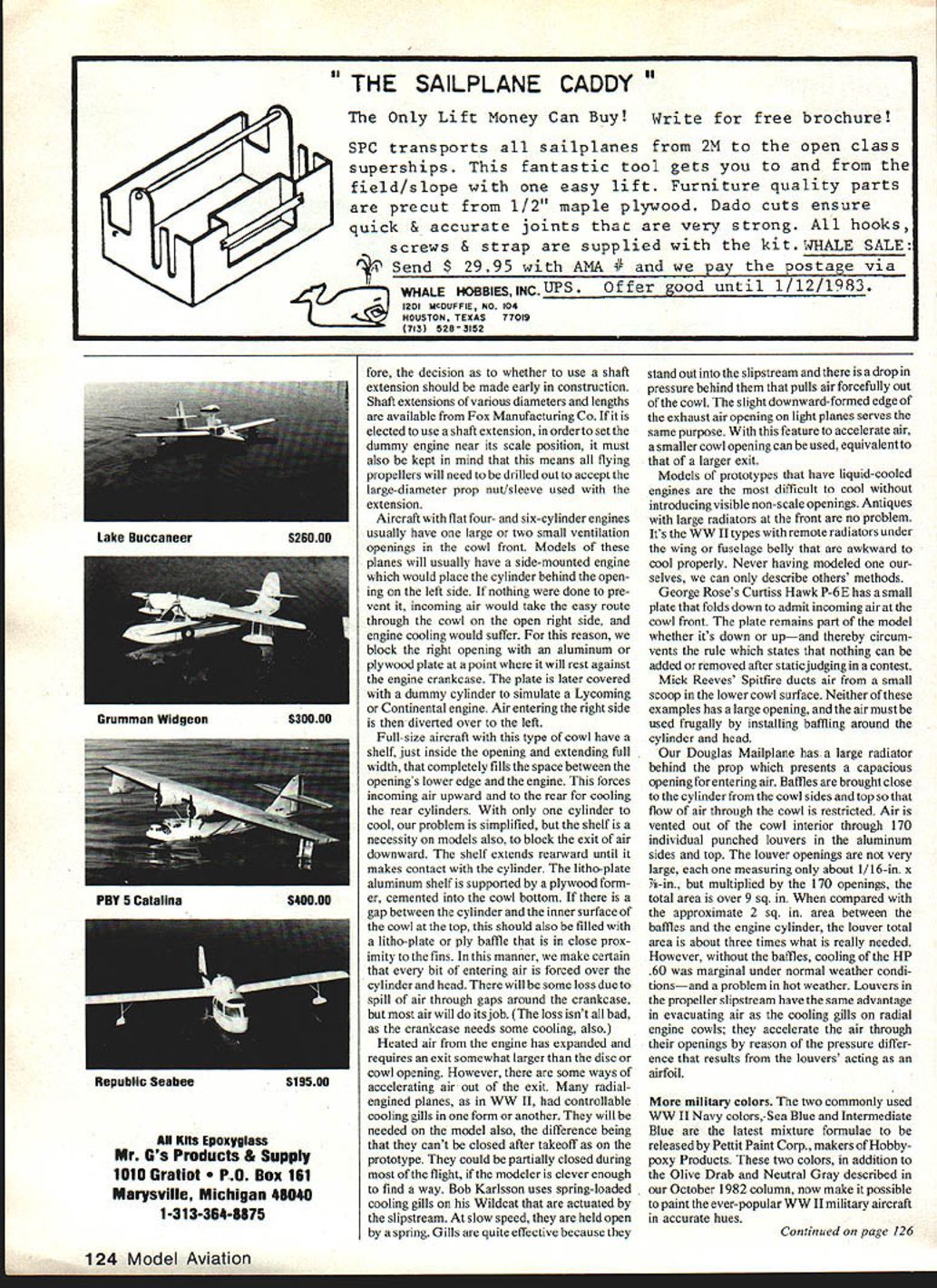
Douglas Mainplane Example
Our Douglas model has a large radiator behind the prop, presenting a capacious opening for incoming air. Baffles are brought close to the cylinder from the cowl sides and top so that flow through the cowl is restricted. Air is vented out of the cowl through 170 individual punched louvers in the aluminum sides and top. Each louver measures about 1/16" x 1/8", and multiplied by 170 openings the total area is over 9 sq. in.
Compared with the approximate 2 sq. in. area between the baffle and the engine cylinder, the louver total is about three times what is really needed. However, without the baffles cooling of the H.P. .60 was marginal under normal conditions and a problem in hot weather. When the propeller slipstream assists evacuation as cooling gills do, the louvers act as airfoils and accelerate the air through their openings by creating a pressure difference.
More Military Colors
Pettit Paint Corp., makers of HobbyPoxy products, has released new mixtures for two commonly used WW II Navy colors: Sea Blue and Intermediate Blue. These two colors, along with the Olive Drab and Neutral Gray described in our October 1982 column, make it possible to paint WW II military aircraft in accurate hues.
Static Judging and Competition
The variability in static judging tells us something about the quality of judging in different classes. The degree of difficulty in judging Precision models is very high, and overburdened judges can be overwhelmed by the task. The more closely grouped Stand-Off scores are often more realistic. It would appear that five Stand-Off judges are easier to find and can do a better job in one-fifth the time.
Examples of inequalities in static judging are seen in the scores of well-known airplanes that appear unchanged in World Championships repeatedly:
- Melleney's Moth Minor: 2,352 (1980) and 2,836 (Reno).
- George Rose's Hawk P-6E: 2,415 (1980) and a low of 1,845 (Reno).
- Jean Rousseau's CAP-20: dropped from 2,659 to 2,249.
- Jack Swift's RV-3: dropped from 2,482 to 1,910.
With pilot abilities being nearly equal, static scores often determine winners. Anyone entering judged events must accept the risks that dictate final placement. Chance plays an important part. Those unwilling to have their work judged by persons of doubtful qualifications can avoid the risk by flying only in Scale Rallies, which are increasing in popularity.
Bob and Dolly Wischer S-221 Lapham Peak Rd., Delafield, WI 53018.
Transcribed from original scans by AI. Minor OCR errors may remain.

