
Radio Control: Scale
Bob & Dolly Wischer
METALWORKING
Anyone with a complete metalworking shop may find the following descriptions elementary, but modelers with minimal equipment will appreciate methods for producing quality metal parts without great expense. Metal components are appearing more frequently on scale models, and the degree of realism possible with metal is significant.
The raw material commonly used is aluminum litho (lithographic) sheet, 0.005–0.010 in. thick. At one time local newspapers sometimes supplied sheets free (used once for a print page); recently they have been worth about 25¢ each as scrap. The stock is quite hard and will be difficult to form into compound curves unless annealed (heated and quenched), so best use is for flat pieces or simple forms. Litho plate arrives with a coating of printer's ink that must be removed. Effective solvents include:
- cleaning fluid
- gasoline
- alcohol
- dope thinner
- acetone
The surface that is etched with printed matter or photos becomes the reverse side of the formed part, so the exterior side will be smooth.
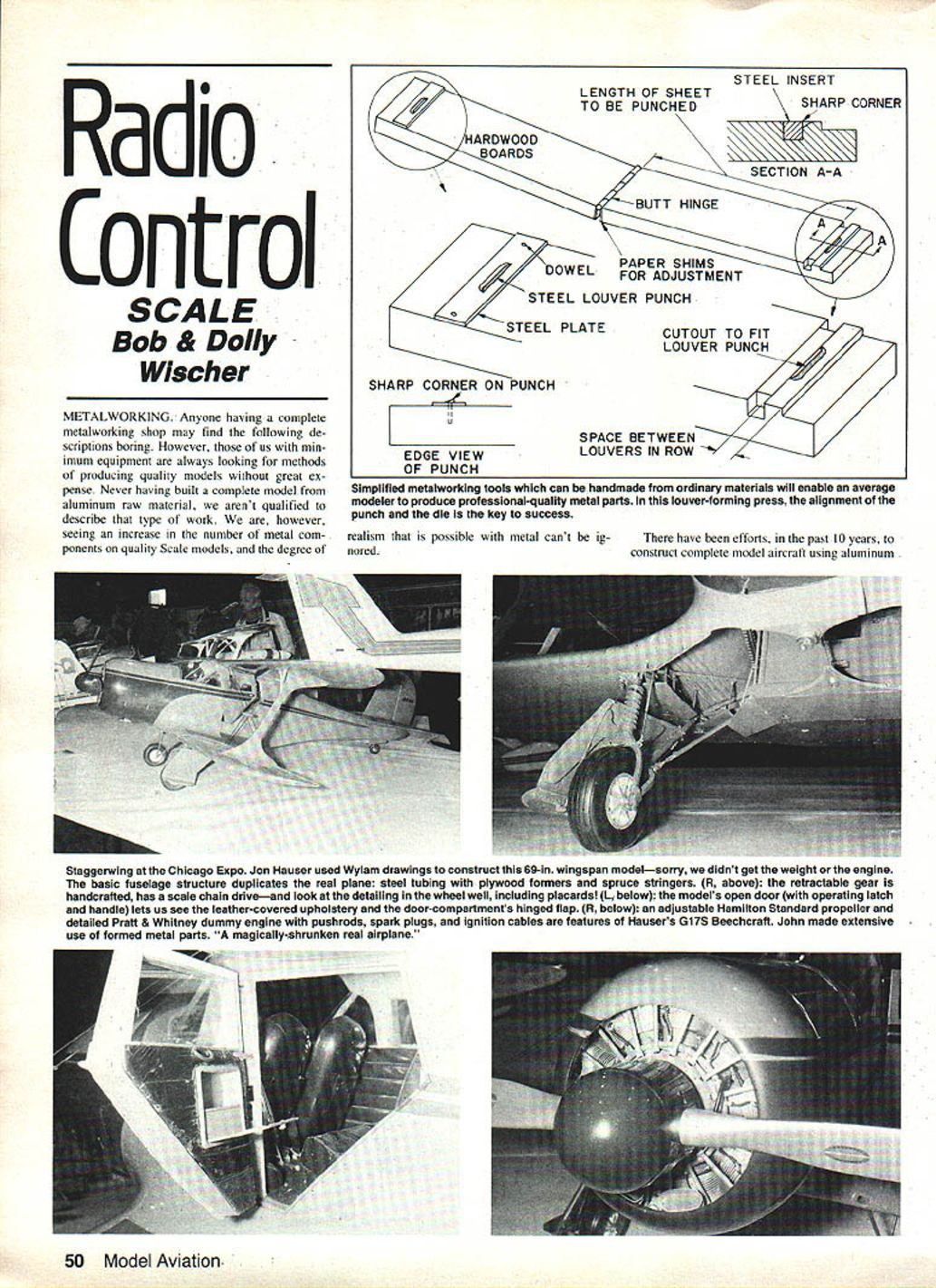
Forming louvers
Most modelers lack elaborate metalworking facilities but can punch louvers from litho sheet using simple hardwood tooling and a small amount of metal at the cutting point.
Materials and basic dimensions:
- Two hardwood boards, about 3/4 × 3 × 10 in. for average work (increase width for longer louvers).
- A cabinet butt hinge, 2-1/2–3 in. long, to hinge the boards at one end.
- A cutting punch filed from a piece of steel to the exact shape and size of one louver.
- A small metal plate to mount the punch (about 1/16 × 3/4 × 3 in.).
- A die block, 1/8–3/8 in. square and about 2-1/2–3 in. long, set into a groove in the lower board.
- Dowels (3/32-in. music wire is ideal) to align the plate to the wood.
Construction and setup:
- File the punch to look exactly like one louver. Solder it to the center of the metal plate.
- Epoxy the punch-and-plate assembly to the upper board, cutting edge toward the hinge, about 1 in. from the end (about 9 in. from the hinge).
- After epoxy cures, drill through the plate into the wood and press in steel dowels to keep the plate aligned.
- Close the hinged boards with the punch resting on the lower board; hammer the top board lightly to mark the die location. Cut a groove across the lower board and set the die block so it is flush with the surface. File the block so its cutting edge is sharp and square.
- Carve a relief in the wood behind the die so the boards come together separated only by the plate and so previously formed louvers are not flattened. Make the relief slightly larger than the punch to compensate for material thickness.
- Adjust the gap between punch and die using paper shims under the die or hinge leaves — too large a gap will tear rather than cut.
Operation tips:
- A light hammer blow will work, but clamping the closed boards together will usually cut .010-in. litho sheet cleanly with less risk of misalignment.
- Use pencil guide lines on the etched side of the aluminum for straight rows.
- Production rate of about 170 louvers per hour was achieved; take care not to overpunch a sheet.
Punch and die (additional notes)
- For alignment, the punch may be soldered to the plate and the plate epoxied to the wood; dowels provide positive alignment and prevent rotation.
- If you need a row of louvers, cut away material from the lower board so each new louver is formed against a fixed edge; this automatically maintains spacing.
Forming corrugations
Corrugated surfaces (ailerons used on Waco, Aeronca C-2, etc.) can be formed using similar tooling. For corrugations, .005-in. sheet is preferred.
Method:
- Use a triangular strip of steel soldered across the plate on the upper board as the punch; it pushes the aluminum into a matching groove in the lower board.
- If lower board wood is hard (birch or maple), the groove can be cut directly into the wood; for softer woods, route the groove into a steel die and epoxy it in place, using the punch as a guide.
- Retain sharp corners where the groove meets the flat surface — these are needed for realistic corrugations.
- The punch height should match or be slightly less than the depth of the groove. A three-cornered file will produce an approximately 120° groove with adequate depth.
- Paper shims under the hinge leaves will aid alignment.
Cutting and forming
Cutting thin aluminum requires avoiding tools that stretch the metal (ordinary tin snips tend to curl and stretch the edge). Better methods:
- Score and break: Use a straightedge and a sharp blade (X-Acto) to score deeply, then bend the sheet over the board edge to snap it along the score. If it doesn't break on the first bend, bend the other way. File the edge lightly to smooth.
- Paper cutter: A long-lever paper cutter will cut aluminum up to .010-in. thick. Always place the workpiece on the cutter board so the unsupported scrap end does not curl. Remove the stressed 1/8-in. or so of stretched metal and the remainder will be flat.
- Bending: Clamp the sheet between two hardwood blocks in a vise and pry the protruding metal over using a third block to distribute force. The inside radius depends on the inside block; very complex shapes can be made in two pieces and joined with CYA cement.
- Z bends and channels follow the same clamped-bend principle.
Rivet detail (embossing)
Rivet detail can be embossed by making impressions on the reverse side of litho plate:
- Use a blunt, rounded tool (a spike filed to a hemispherical tip works).
- Lay the part face down on a lead or hardwood block and tap the tool with a light hammer.
- Practice on scrap to determine required hammer force and tool size.
- For many rivets, consider mounting the forming tool on the end of a pivoted lever and using a falling weight for uniform blows, or use a dimpled steel block for consistent impressions — techniques borrowed from scratch-builder model railroaders.
Benefits and finish
Metalworking is a valuable skill for scale modeling. Metal parts often need little or no paint; if painted, use a primer first to assure adhesion.
New FAI rules
The new FAI static scoring and proof-of-scale rules simplify documentation required for scale contests:
- Proof of scale: a three-view drawing between 1/24 and 1/72 scale, with a minimum wingspan of 150 mm (5.91 in.). For older prototypes, a selection of photos may substitute for the three-view.
- Proof of color and markings: from an authentic source (for example, a Profile). Provide at least three photos, including one of the actual subject being modeled.
- The contestant must certify that he/she built the model and supply a declaration listing components not made by the builder.
- Proof of prototype cruising speed must be furnished.
- A scale ruler is no longer required.
- There is no limit on the number of photos or pages in the presentation.
- A simplified judges' guide explains how to place the model for checking against the three-view and photos. Specific items for checking are listed, and photos take precedence over three-views where they conflict.
- Flight judging and the complexity bonus remain unchanged.
Static judging details:
- Under the new rules, cockpit detail is considered part of scale detailing and cannot be examined closely. Judging distance for the whole airplane is 1 m (39 in.). The model will be repositioned so it can be viewed from the side, front, rear, top and bottom.
- Craftsmanship is now a primary factor in static scores, with a K-factor of 10 — equal to scale accuracy. This differs from AMA Sport Scale rules, where craftsmanship is less apparent from distance.
Event application and references:
- The Nats planning committee decided to use the new FAI rules for the Precision Scale event at the 1983 Nats.
- The new static judging schedule and changes in displacement allowed for four-stroke engines were published in the April 1983 column.
- For details, see the AMA rule book: sections 4.2.5 and 1.9 (Proof of Scale).
Transcribed from original scans by AI. Minor OCR errors may remain.

