
Radio Control: Scale
Bob & Dolly Wischer
New RC Frequencies
At a recent local RC meeting, District VII Frequency Coordinator Pete Waters presented charts showing locations of industrial transmitters that could threaten flying RC models. He disclosed that a local telephone company had built a transmitter on a commonly used RC frequency (75.64 MHz) only a few miles from the club flying field. Without Pete’s help the club might have continued using 75.64 MHz until someone’s model was shot down. That loss could have been a trainer built in weeks—or a Scale model requiring some 2,000 hours.
Scale modelers, in particular, need the Frequency Coordinator’s assistance to be reasonably certain their club field is not within range of such transmitters. Coordinators’ names and contact information are listed in the heading of the Vice-President’s column in AMA News. Chartered clubs should contact the Coordinator in their district and give the exact location of their fields. Contest directors who conduct Scale events should also be aware of which frequencies are usable.
A word of caution: some experienced fliers tend to discount interference reports, considering “interference” a scapegoat for other problems. Until new narrow-band receivers are widely adopted, moving to a new frequency may not always avoid local interference. Before flying a valuable Scale aircraft, check the local frequency situation.
Composite construction
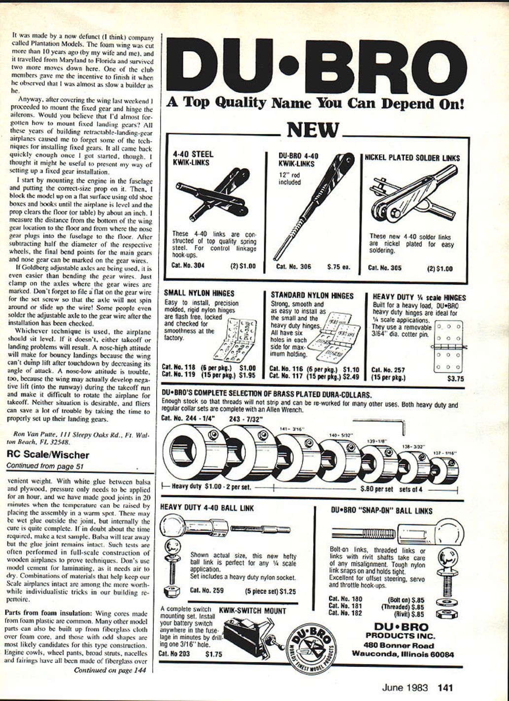
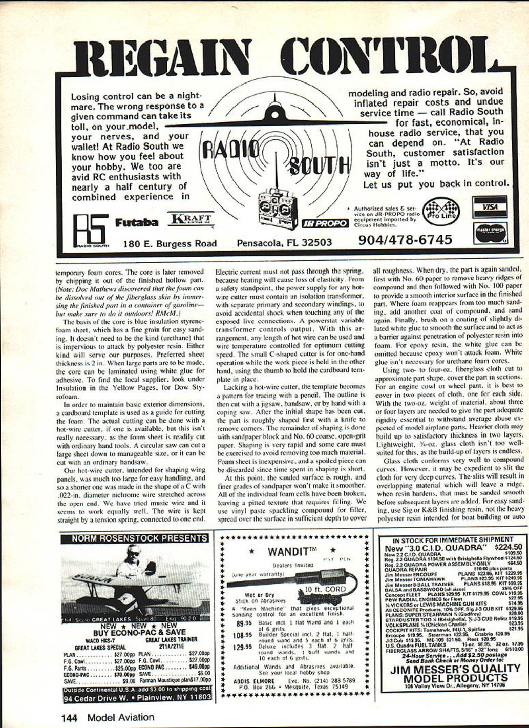
In spite of a near-vertical descent onto the apron at Reno, our Ryan SCW required surprisingly few new parts during reassembly. The fuselage aft of the wing spar was completely demolished; the Supertigre engine needed a new shaft and crankcase. The wings were recovered with only a couple of cracked ribs replaced. The stub spar through the wing center section (which mounts the landing-gear legs) was badly shattered and required replacement.
The original stub spar had been built as a sandwich: a 1/4-in. balsa core laminated between 1/16-in. plywood outer skins. We considered a seven-ply, 3/32-in. plywood spar to save weight and fabrication time, but the plywood spar proved too flexible and failed in service. A new stub spar duplicated the original lightweight sandwich construction and had much greater rigidity—well worth the extra build time.
Throughout construction of the Ryan, at least a dozen applications of thin plywood laminated to balsa were used. The airplane’s eventual survival indicates the value of this technique. Lamination with white glue under pressure yields high strength with minimum weight penalty.
When to use composite bulkheads
Main load-bearing bulkheads are classic locations for composite construction. Prototype bulkheads often have small cross sections; balsa alone would be weak. Adding a thin layer of plywood (1/64–1/32 in.) to exterior flat surfaces converts a weak part into an effective load-bearing piece and improves realism. Edges laminated with ply have a sharp profile that is difficult to obtain with balsa alone; this is valuable where parts mate (for example, wing-to-fuselage joints), because the plywood butting surface gives a much cleaner, less conspicuous joint line. For maximum strength without regard to cost, use graphite sheet for laminating.
Pressure, clamping and adhesives
- Use C-clamps to apply pressure while laminating. Sandwich the part between flat boards and use waxed paper to keep glue off the boards.
- Parts only need to be wetted with glue; surplus is squeezed out under pressure. If C-clamps are unavailable, use a stack of heavy books or other convenient weights.
- With white glue between balsa and plywood, pressure only needs to be applied for about an hour at normal temperature. In a warm spot the cure may be effectively complete in 20 minutes.
- Don’t use model cement for laminating—model cement needs air to dry and won’t produce the same strong laminate.
- If unsure about cure time, make a test sample: try tearing away the balsa—if the glue joint remains intact the lamination is sound.
Parts from foam insulation
Materials
- Core: blue insulation styrene-foam sheet (fine grain, easy to sand). Preferred thickness: 2 in.
- Filler: vinyl spackle compound to fill the pitted foam surface.
- Barrier coat: slightly diluted white glue brushed on to prevent polyester resin from penetrating the foam (not necessary with epoxy resin; not needed for urethane foam cores).
- Glass cloth: 2–4 oz. fiberglass cloth; for most cowlings or wheel pants use 2–oz cloth with 3–4 layers for adequate rigidity.
- Resin: use light finishing resins (Sig or K&B) rather than heavy boat-building polyester resins when easy sanding is desired.
Note: You can use either styrene or urethane foam for cores; styrene is easy to sand. For suppliers look under Insulation in the Yellow Pages (e.g., Dow Styrofoam).
Cutting and shaping the core
- Use a cardboard template as a guide for cutting the foam.
- Cutting tools:
- Hot-wire cutter (preferred for smooth outlines).
- Circular saw or jigsaw to cut large sheets down.
- Handsaw or coping saw for manual cutting.
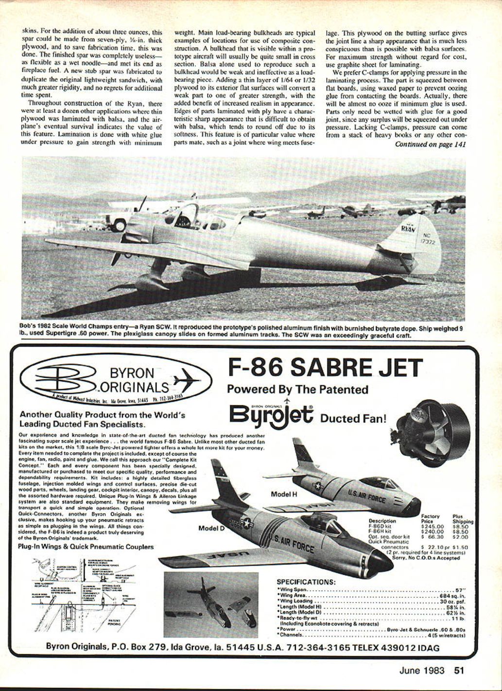
- After rough cutting, remove corners with a knife and shape with a sandpaper block using No. 60 coarse, open-grit paper. Take care to avoid over-sanding; foam is cheap and quick to replace if spoiled.
Hot-wire cutter and safety
- Our small C-shaped hot-wire cutter uses .022-in. diameter nichrome wire stretched across the open end. Music wire works as well. Keep the wire straight with a tension spring attached to one end, but do not pass current through the spring (heating will weaken it).
- Power supply must include an isolation transformer (separate primary and secondary windings) to avoid accidental shock from exposed connections. Use a Powerstat variable transformer to control output and wire temperature.
- One-handed small cutter operation is convenient: hold the workpiece in the other hand and use the thumb to hold the template in place.
- Safety note: always use the hot-wire cutter with the isolation transformer in place and perform work where fumes and dust are safely managed.
Filling and finishing foam cores
- After shaping, the sanded foam surface will be pitted. Apply vinyl spackle compound over the surface to fill roughness.
- When dry, sand first with No. 60 to remove heavy ridges, then use No. 100 for final smoothing.
- Where foam reappears from over-sanding, add another coat of compound and sand again.
- Brush on a coating of slightly diluted white glue as a barrier if you plan to use polyester resin. If using epoxy resin, the glue barrier is unnecessary.
Fiberglass layup
- Cut 2–4 oz. fiberglass cloth to approximate part shape and cover the part in sections. For cowlings or wheel pants, cover each side separately.
- Using 2-oz cloth, apply about three or four layers to achieve adequate rigidity. Heavier cloth may require fewer layers; very lightweight 4-oz cloth may require many layers to build thickness—plan accordingly.
- For deep curves you may need to slit the cloth; slits cause overlapping that will leave a ridge after the resin cures and must be sanded before additional layers are added.
- For ease of sanding use light finishing resins (Sig or K&B) rather than heavy polyester intended for boat building or auto work.
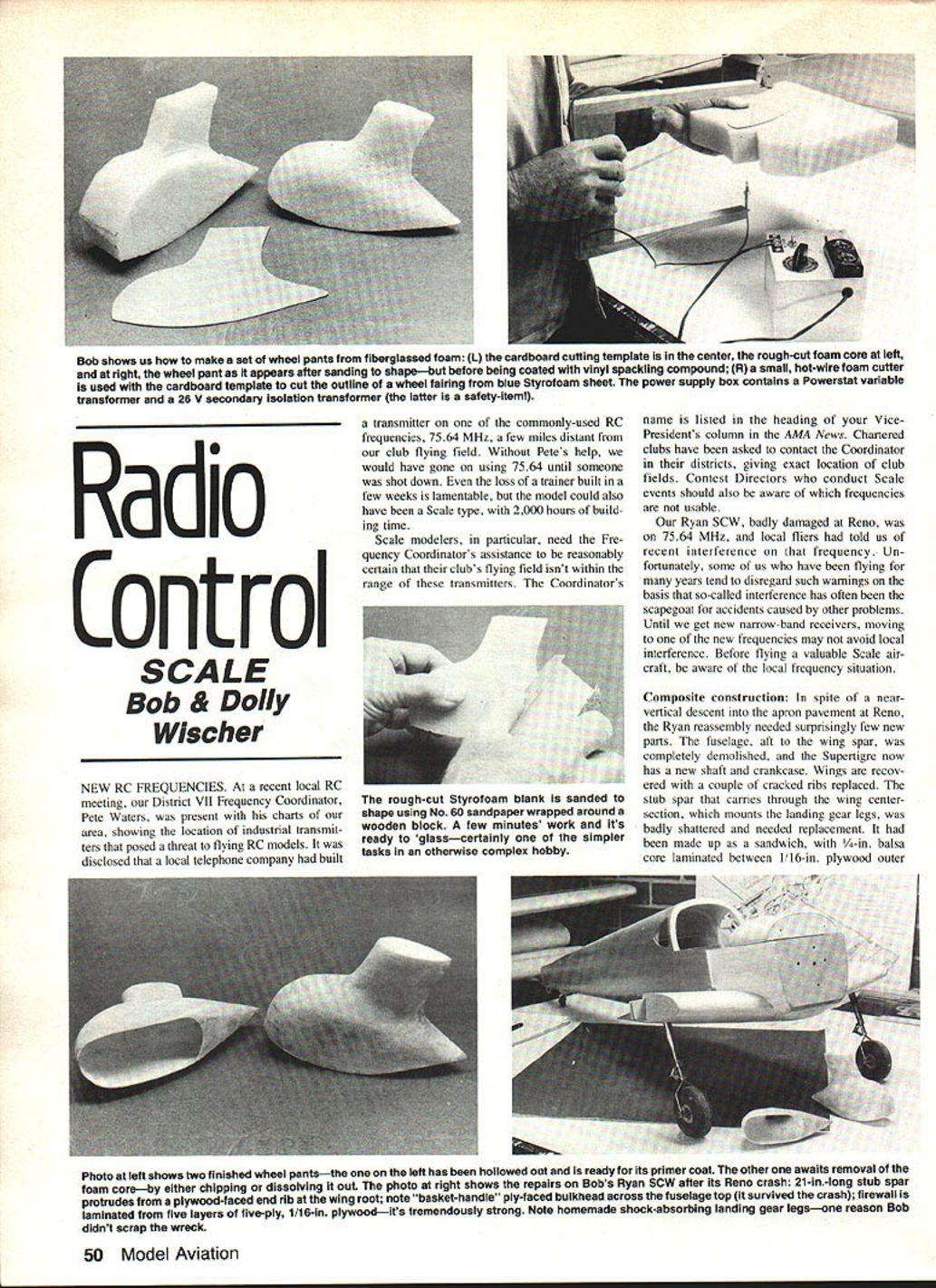
Example: wheel pants
- Rough-cut foam cores from blue Styrofoam using a cardboard template.
- Shape with knife and sanding block, fill with vinyl spackle, sand smooth, apply barrier coat if needed, then fiberglass and resin in multiple layers for strength.
- A small hot-wire cutter and a power-supply box containing a Powerstat variable transformer and an isolation transformer make an effective, safe setup for cutting cores.
Final notes
Composite construction—thin plywood laminated to balsa and fiberglass skins over foam cores—offers an excellent balance of strength, weight, and realistic appearance for Scale modeling. Careful selection of materials, proper clamping and curing techniques, and adherence to hot-wire cutter safety will yield durable, attractive parts that stand up to the demands of flying and scale competition.
Transcribed from original scans by AI. Minor OCR errors may remain.

