
Radio Control: Scale
Bob & Dolly Wischer
Aeronca K lives again
Forty-three years ago, as newlyweds in search of adventure, we bought a four-year-old Aeronca K for $650. With scale-modeling friends, we began flight training, each of us investing $217. After 50 hours the Department of Commerce flight inspector insisted we "get a better airplane" for flight tests because of the Aeronca's two‑cylinder engine, single ignition, and lack of wheel brakes. Our partners declined to invest further, so we continued training in a Lycoming‑powered Taylorcraft for another $600. The T‑craft had four cylinders (single ignition) and heel‑operated wheel brakes that were nearly useless, but it satisfied the inspector and we earned our pilot's licenses.
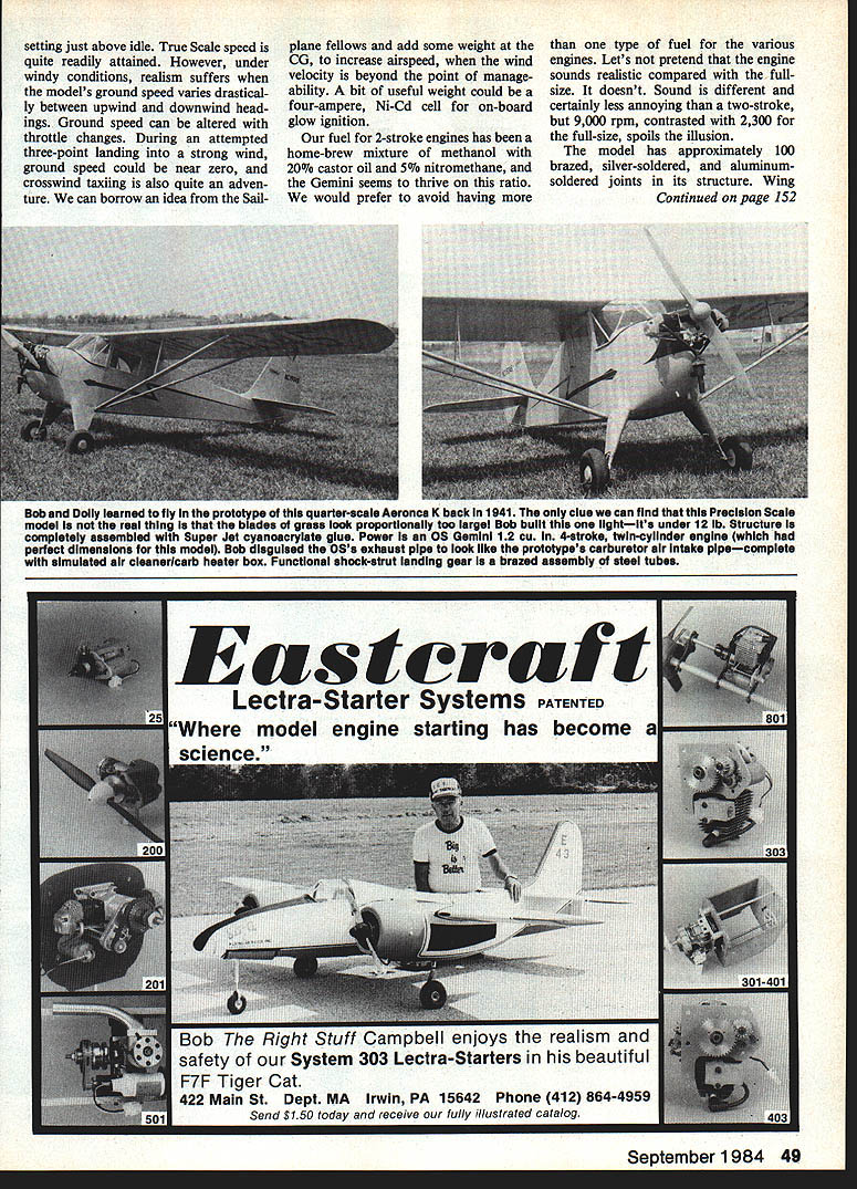
Being avid scale modelers, we measured and photographed both airplanes and made drawings with the intent to reproduce them in model form. Forty‑three years later a quarter‑scale, nine‑foot‑span Aeronca K was finished and flying, built from our drawings together with Paul Matt's drawings in Historical Aviation Album, Volume 15. Coincidentally, the license number on Paul's drawings, NC19345, was our airplane; one Album photo even shows it parked in front of our hangar at Milwaukee's Mitchell Field. As with all our scale models, the K was built from a few pencil lines—there were no model construction drawings.
The decision to build the Aeronca quarter‑scale was aided by the close similarity of an O.S. Gemini 1.20 twin to the Aeronca two‑cylinder engine. Its overall dimensions are almost correct; only the shaft length is too long. The scale propeller hub was counterbored on its back side to compensate for the added length, and the Gemini crankcase was disguised with sheet aluminum to simulate the Aeronca case casting.
The project began as a Sport Scale airplane that could be flown in Giant Scale competition and, in final form, can also compete in FAI Precision class. At 12 lb it is well within weight limits; wing loading is about 20 oz per sq. ft.
Lightweight Sig Aeroscale wheels had their ribbed treads ground off smooth to improve scale appearance. Grinding was done by placing the wheel on a shaft (lubricate the bearing) and pressing the ribbed tire tread against a spinning sanding disc at an angle so the tire slowly revolves while excess rubber is removed. The trick is setting the shaft angle so the tire isn't spun too rapidly. The result is a rapid, uniform removal producing a scuffed surface that looks like a tire that has seen many landings.
The Aeronca is covered with Sig Koverall and heat‑shrunk using a medium setting on the heat‑sealing tool—too much heat will collapse light structure. After shrinking it received three coats of non‑tautening butyrate dope and two coats of color for a lightweight finish.
Because the model is light, it has a very wide speed envelope. At full throttle the speed is obviously too high for scale realism; the model will float along without losing altitude at a throttle setting just above idle, so true scale speed is readily attained. Under windy conditions realism suffers because ground speed varies drastically between upwind and downwind headings; ground speed can be altered by throttle changes. During an attempted three‑point landing in strong wind, ground speed could approach zero, and crosswind taxiing becomes challenging. Sailplane pilots sometimes add weight to increase airspeed when wind velocity becomes unmanageable; a useful option is a four‑ampere Ni‑Cd cell for on‑board glow ignition.
Our fuel for 2‑stroke engines is a home‑brew mixture of methanol with 20% castor oil and 5% nitromethane; the Gemini thrives on this ratio. We prefer to avoid multiple fuel types for different engines. We won't pretend the engine sounds exactly like the full‑size—the model runs around 9,000 rpm versus about 2,300 rpm for the full‑size, which spoils some of the illusion.
Construction includes approximately 100 brazed, silver‑soldered, and aluminum‑soldered joints. The struts, made of gum hardwood, have 24 silver‑solder joints in the fittings alone. Some aluminum soldering was done on hobby‑shop tubing with .015‑in. wall thickness; too much heat melts the parts, too little keeps the solder from flowing.
Two critical factors determine success in brazing, aluminum‑soldering, and silver‑soldering small parts:
- Flame intensity must be completely adjustable and only applied long enough to obtain good fillet flow.
- Brazing‑rod diameter must be appropriate; if the rod is too large, it requires more heat to melt than to heat the parts, risking damage.
As models get lighter, we increasingly use scrap hardware to join light metal pieces; brazed joints provide significant strength from small, light parts, helping reduce overall weight.
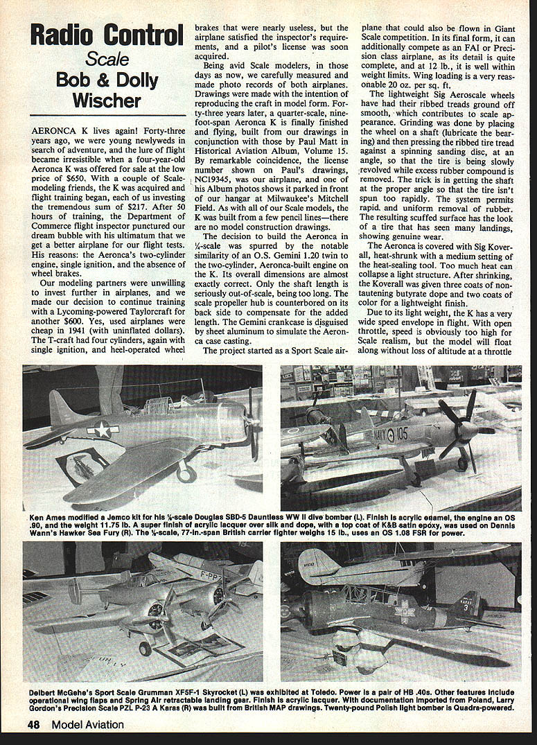
Other builders have produced fine scale models and finishes: Ken Ames modeled a 3/8‑scale Douglas SBD‑5 Dauntless with acrylic enamel over silk dope; Dennis Wann built a 7/8‑scale Hawker Sea Fury (77‑in span) using an OS 108 FSR; Deibert McGehe exhibited a Sport Scale Grumman XF5F‑1 Skyrocket using twin HB .40s. Features seen in various models include operational wing flaps, Spring Air retractable gear, and acrylic lacquer finishes. Documentation can be imported—Larry Gordon's Precision Scale PZL P‑23 Karas was built from British MAP drawings—and builders have tackled a wide range of subjects including quad‑powered Polish bombers.
Our Aeronca K was ultimately destroyed in a windstorm (described as a tornado). Of a hundred airplanes at the airport, it was the only one damaged—new hemp ropes were torn as it went over the fence and inverted. Only the engine and landing gear were salvageable; the engine brought $100.
Bob and Dolly Wischer S‑221 Lapham Peak Rd., Delafield, WI 53018
Incidence angles
Longitudinal dihedral, the angular difference between wing and stabilizer incidence, is typically greater on full‑size airplanes than on our scale models—especially on aircraft built in the 1920–40 era. On the Aeronca K there is a 4° negative incidence of the stabilizer (leading edge lower than the hinge line) combined with a 2° positive incidence of the wing for a total difference of 6°, measured relative to the thrust line or horizontal fuselage reference line.
Examples:
- Beechcraft 17 Staggerwing: about 5½° longitudinal dihedral plus 2½° downthrust
- Aeronca Champion: about 4½°
- Taylorcraft: about 5°
These differences are often visible from a side view. If the thrust line and stabilizer appear parallel while the wing is set at a positive incidence, the airplane will fly tail‑high and exhibit built‑in downthrust. On some airplanes, tail surfaces work in disturbed air (wing downwash), which affects the effective angles. Some aircraft have adjustable stabilizers (for example, from −5° to +2°).
The angular difference promotes pitch stability: if the nose drops, speed increases and the negatively‑set stabilizer produces down‑pressure to raise the nose; if the nose rises, speed decreases and stabilizer down‑pressure is reduced to lower the nose. A negatively set stabilizer will stall after the positively set wing, helping retain control in stall maneuvers and three‑point landings. However, excessive stabilizer down‑pressure at high dive speeds, combined with sudden up‑elevator, can risk structural failure. Note that wire bracing on scale model tail surfaces is functional.
Longitudinal dihedral induces drag. Pilots have used slight dives and trimmed nose‑down, holding more down‑elevator with forward control pressure to reduce wing angle of attack and induced drag—tricks used to increase airspeed and conserve fuel on long flights. This technique can be tiring on long legs but produced 5–10 mph gains in speed in full‑size practice.
For RC scale models we typically reduce the prototype's angular difference to about 2° total. Reasons:
- Full‑size engines often constitute 1/4–1/3 of total weight, shifting CG forward; models with lighter engines require nose ballast to match prototype CG.
- Flying with constant down elevator burdens the elevator servo, causing extra battery drain, high drag, and pitch‑varying "tab" effects.
- Excessive angular difference gives too much pitch stability for radio control; we prefer control responsiveness rather than the excess stability required for Free Flight Scale.
Practical setup recommendations:
- Balance the model at about 25%–30% of wing chord aft of the leading edge, preferably by shifting tanks, batteries, and radio equipment rather than adding excessive nose weight.
- Changing stabilizer incidence affects elevator travel requirements. For taildraggers, allow extra up‑elevator travel to ensure the tailwheel can be brought down for a neat three‑point landing. As speed approaches stall, elevator effectiveness falls.
- For the Aeronca full‑stall landing we used about 20° of up‑elevator travel. Down‑travel is less critical for non‑aerobatic types; for aerobatic models (except those with fully symmetric airfoils) provide more down than up.
- Tailspins and snap rolls require substantial up‑elevator; for these maneuvers 20° of up travel may still be marginal, so include an adjustable elevator travel stop in the linkage to ensure sufficient movement.
Our K model enters a slow, controlled spin on command and stops immediately when controls are neutralized, confirming the effectiveness of the control setup.
(End)
Transcribed from original scans by AI. Minor OCR errors may remain.

