
Radio Control: Slope Soaring
Wil Byers Rt. 4, Box 9544 West Richland, WA 99352
Fuselage jig (Mike Mellor)
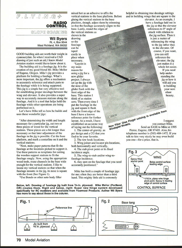
Good building aids are worth their weight in cyanoacrylate. When I received a CAD drawing of a particularly useful aid — a fuselage jig — I knew Model Aviation readers would like to know about it. The jig, created by Mike Mellor of Eugene, Oregon, provides a platform for holding a fuselage and a mechanism to accurately reference and attach parts while the fuselage is supported. It is a simple but effective tool for establishing proper decalage between wing and elevator, accurately measuring stations along the fuselage, and holding the fuselage during other operations.
Mike describes how he builds and uses these jigs:
Building the jig
- Determine the necessary width and length for the jig and cut two or three pieces of wood for the vertical stations. Make these pieces a bit longer than necessary to allow later adjustment.
- Cut the base platform and mark a centerline on the base and the vertical stations.
- Make paper patterns that fit the fuselage at the chosen support locations. Use the patterns as templates to cut wooden support stations to fit the fuselage snugly.
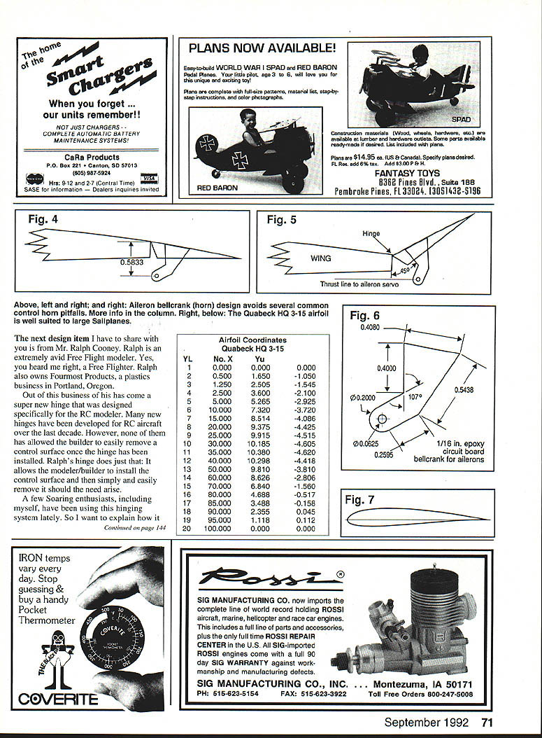
- Route channels in the base wide enough for the vertical stations. Locate the vertical stations so that when the fuselage mounts in the jig its nose is square with the front of the base.
- Use Bondo or another auto-body filler (mixed hot) as an adhesive to affix the vertical stations to the base. Before gluing, trim and adjust the stations so the fuselage aligns accurately to the base.
- Round the edges of the vertical stations so the fuselage can be taped easily in place when necessary.
Using the jig
Layout is the main reason Mike uses a jig for new glider projects. He always sets the jig with the nose of the glider flush with the front edge of the base — station zero. Every time the fuselage is squared flush with the front edge, he has a known reference point for further layout tasks. Using this reference he lays out:
- The center of gravity, per design and a preferred CG.
- The tow hook locations.
- Wing joiner and locator pin locations, both horizontally and vertically.
- The stab pivot point or fixed incidence angle.
- The wing-to-stab and/or wing-to-fuselage incidence.
- Any spot on the fuselage that needs accurate positioning.
Mike’s jigs are often better than a third hand. For example, one fuselage in the jig had the elevator referenced to 0° angle of attack relative to the jig surface; the wing could then be referenced to the jig rather than to the elevator, making decalage and incidence setup much easier.
Contact Mike Mellor for help or to purchase a jig: 1995 Pierce, Eugene, OR 97405. Telephone: (503) 484-1472.
Removable hinge (Ralph Cooney / Fourmost Products)
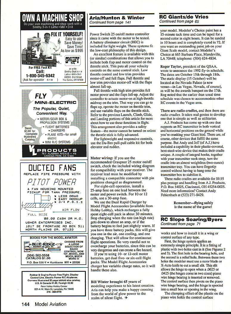
Ralph Cooney of Fourmost Products (Portland, Oregon) developed a new plastic hinge specifically for RC modelers that allows a control surface to be installed and later easily removed. The hinge is a small plastic fitting with two cast holes: a bearing hole and a relief hole. Between the two holes you cut a small slit with a razor blade; this slit allows the hinge to open when a piano-wire hinge bearing is inserted or removed. The control surface pivots on the piano-wire bearing, and the plastic clamps the wire to hold the surface securely. With multiple hinges per surface and the plastic’s clamping strength, the system is reliable even at high speed.
A few modelers, including myself, have used this hinging system successfully — even in near-terminal high-velocity dives — and it performs well.
Installing the hinge
- Construct the control surface and the socket in the wing that will receive the hinge.
- Cut a horizontal slot in the leading edge of the control surface, centered and 3/4 to 1 inch long, wide enough for the piano-wire hinge pivot.
- Use a Dremel or similar tool to cut a vertical slot in the control surface for clearance of the hinge tang during movement.
- Cut the piano wire to length and snap it into the hinge. Cut between the relief hole and the bearing hole with a very sharp razor blade.
- Epoxy the piano wire into the horizontal slot in the leading edge of the control surface, centering it within the vertical slot. Allow the epoxy to dry.
- Make anchor boxes in the trailing edge of the wing socket where the hinge bases will fit.
- Place four or five strips of paper along the trailing edge socket as clearance gauges. Stand the wing on its leading edge, fill the anchor boxes approximately halfway with epoxy (do not overfill), and push the control surface down so the hinge bases go into the anchor boxes. Tape the surface in place and allow the epoxy to cure.
- After curing, remove the paper gauges and tape. The control surface should move freely and can be removed by moving it downward or upward to force the hinge open and release the bearing.
To purchase these hinges, contact Fourmost Products, Inc., 4040 24th Avenue, Forest Grove, OR 97116. Telephone: (503) 357-2732.
Airfoil coordinates — Quabeck HQ 3-15
YL No. X Yu 1 0.000 0.000 0.000 2 0.500 1.650 -1.050 3 1.250 2.505 -1.545 4 2.500 3.600 -2.100 5 5.000 5.265 -2.925 6 10.000 7.320 -3.720 7 15.000 8.514 -4.086 8 20.000 9.375 -4.425 9 25.000 9.915 -4.515 10 30.000 10.185 -4.605 11 35.000 10.385 -4.620 12 40.000 10.298 -4.418 13 45.000 8.860 -2.800 14 50.000 6.840 -1.560 15 60.000 4.688 -0.515 16 70.000 3.488 -0.045 17 80.000 2.355 0.045 18 90.000 1.118 0.112 19 95.000 0.000 0.000 20 100.000 0.000 0.000
(Note: hinge hardware sizes available: .0625 in. and .0425 in. piano wire bearing; the bellcrank described later uses 1/16 in. epoxy circuit board.)
Aileron bellcrank design and installation
Aileron bellcranks transfer motion from a servo to the aileron without binding, loss of motion, or input slop. They should allow for aileron differential, be linear, and avoid binding against the wing bottom at extreme deflections. Common problems include improper geometry, pushrods hitting the wing, or non-linear linkage.
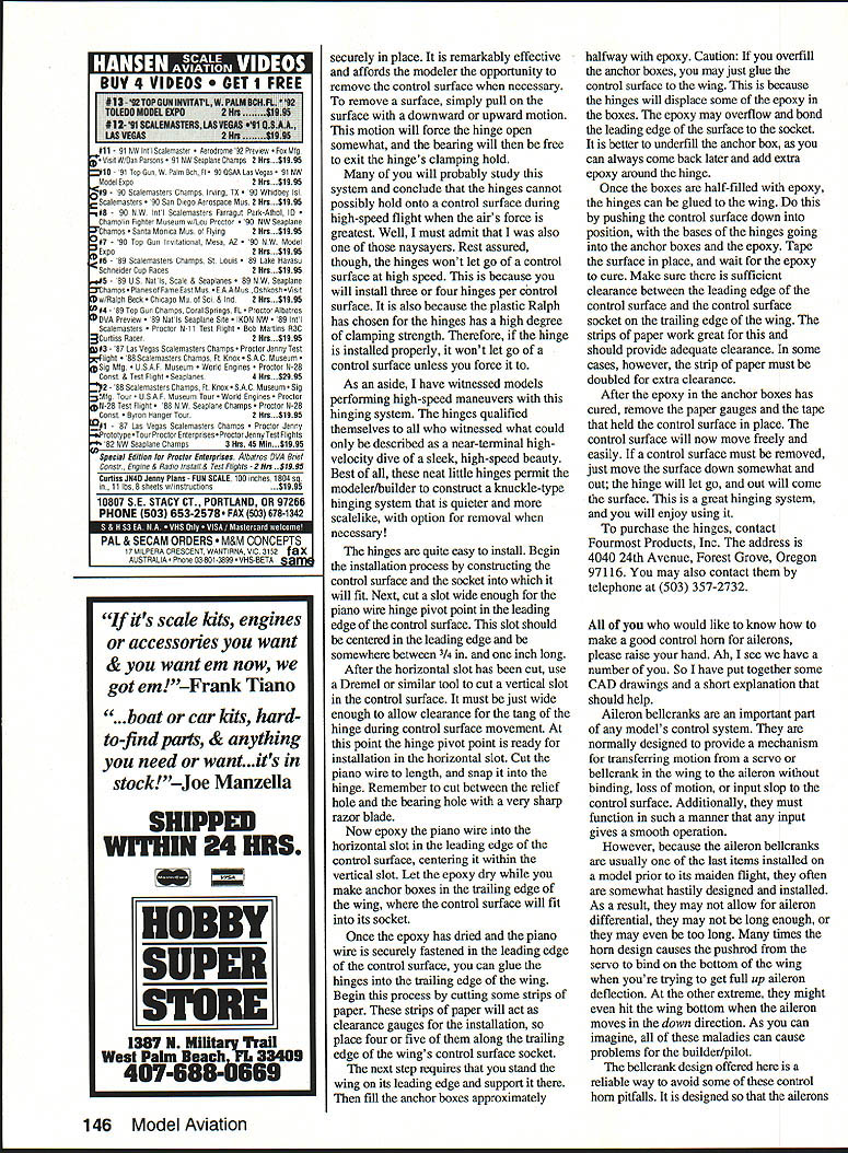
The bellcrank design shown here avoids several pitfalls:
- Allows aileron travel exceeding 45° up and 25° down.
- Keeps the servo/wing bellcrank attachment perpendicular to the control surface hinge point for linear input.
- Prevents the pushrod from hitting the wing bottom even at large up deflections.
- Constructed from 1/16-inch epoxy circuit board for strength.
Installation:
- Cut a slot in the bottom of the aileron to the width and length of the bellcrank.
- Sand the bellcrank slightly for good epoxy adhesion.
- Fill the slot about half full with epoxy and set the horn in the slot.
- Ensure the horn is square to the aileron and that the pushrod hole aligns with the hinge point.
- Allow the epoxy to cure.
CAD for model design
Mike and I used computer-aided-design programs to generate drawings. Mike uses AutoCAD (AutoDesk) on a 486 IBM-compatible computer. I use AutoCAD Release 11 on an IBM 386 and ClarisCAD on a Macintosh.
- AutoCAD Release 11: powerful 2D and 3D drafting and design; extensive command set and AutoLISP programmability; around $3,000.
- ClarisCAD: two-dimensional drafting for Macintosh; mouse-driven, user-friendly, strong pull-down help; about $700; lacks 3D and AutoLISP.
- AutoSketch (AutoDesk) is a more affordable 2D option for PC users (around $1,000).
Both programs are useful for modelers entering computer drafting; expect a learning curve.
Fiber Glas Flugel catalog and Windspiel Models
Fiber Glas Flugel’s new 1993 color catalog is available from Windspiel Models, P.O. Box 2121, Coeur d’Alene, ID 83814. Windspiel is a small import business owned by long-time RC scale-soaring enthusiast Peter Bechtel. Windspiel imports Fiber Glas Flugel’s molded scale sailplanes, which arrive nearly ready to fly, gel-coated white with realistic finishes and precision-hinged control surfaces.
One featured model is the ASH-25 with a 2.5-meter span (≈98.5 inches) and a realistic scale aspect ratio of 37:1. These molded ships are excellent for slope soaring and weak-lift penetration due to their high aspect ratios and the Quabeck HQ 3-15 airfoil. Windspiel can be contacted by phone at (208) 667-0070.
Airfoil: Quabeck HQ 3-15 (description)
The HQ 3-15 is a 15% thick airfoil with 3% camber (3% of chord), developed by Dr. Helmut Quabeck. Its moderate camber yields a good lift coefficient without excessive drag. For comparison, the Euler 2-14 has mean camber ~4.03% and the Selig/Donnawan S-D-800 ~1.71%; the HQ 3-15 falls between these in camber and expected Cl.
This section suits large-scale models with high aspect ratios that require thickness for structural strength. While it may cost some profile drag, increased aspect ratio reduces induced drag, and the thicker section can carry higher wing loading — a common requirement of scale models. The HQ 3-15 also adapts well to flaps to vary camber and lift coefficient. Try it on your next open-class replica and report your results.
Transcribed from original scans by AI. Minor OCR errors may remain.

