
Radio Control
Slope Soaring
Mark Triebes 20794 Kreisler Ct. Saratoga, CA 95070
DESIGNING a Slope ship
Without a doubt, the recent proliferation of slope-soarer kits has made it much easier to find a plane that fits your needs. Still, it can be difficult to find the ideal ship. Maybe you want a plane that will rip and tear at a small slope doing high‑G, gut‑wrenching maneuvers; maybe you want one that will use up lots of airspace with huge, fast, smooth maneuvers. Whatever your ideal slope‑site plane might be, the best way to get exactly what you’re looking for is to design the plane yourself.
Designing a slope ship is not easy: a lot of time and effort go into designing and refining a sailplane. Anyone who says differently either is selling something or has never tried it. Occasionally you will come across a plane that flies great right off the board, but these are few and far between. Most designs take months or years of research, design, construction, testing, redesign, and more testing before achieving the desired results. Although time‑consuming, the process is immensely fun and incredibly rewarding when the plane reaches its final form.
If you’ve had the urge to design but weren’t sure where to start, the following guidance (inspired by Pete Marshall’s "Looking for Miss Go‑Fast" in Slope Soaring News) gives basic parameters to get you moving.
Learn before you draw. If you say “can’t draw, can’t build,” grab pencils, erasers, rulers, French curves, and lots of drawing paper. Start sketching until the shape looks right — but first, read some stuff.
Fuselage
- Basic function: hold the wing and tail apart at the proper incidence angle.
- Other uses: provide room for full radio gear and ballast (lead).
- Shape: not critically important. Pick a shape you like (Miss Go‑Fast could be a DeHavilland Dash 8, a Reno P‑51, or anything that inspires you). Stay within overall design parameters.
Wingspan
- Range: 60–80 in.
- Optimum: 70–78 in.
If you want to go really fast you often have to get high; if you want to get up high and still see the plane you need wingspan. Other things being equal, big wings tend to fly better than small wings.
Aspect ratio
- Formula: aspect ratio = span^2 / wing area.
- Range: 8:1 to 11:1.
- Optimum: 10:1–11:1.
With an aspect ratio below about 6:1, soarability drops noticeably at high wing loadings: the airplane won’t climb out well or climb very high.
Sweepback
- Leading edge: less than 10°.
- Trailing edge: less than 5°; optimum: 0°.
Jet‑like sweepback does not enhance loop/roll maneuvers and it increases pitch stability (similar to dihedral effects in roll).
Dihedral
- Optimum: 0–2°.
- If you use 0° dihedral, wings may appear to droop in the center—add a 1–2 in. block under one wing half when joining to make the wings look right in the air.
- Avoid dihedral over 5° — too much roll stability reduces roll agility.
Airfoil section
- Reliable choices: Eppler 374 or RG‑15.
- Newer option: Selig SD6060 (an enhanced Eppler 374 variant).
- Thickness considerations:
- Tight sites / limited operating space below crest: use 9–11% thickness for better low‑Reynolds behavior; these thinned sections are faster and support tight, high‑G maneuvers but need higher speed to work well.
- Large hills / big lift: use a 7.5% Eppler 374 to keep Reynolds number high and smooth — a fast airfoil for big‑sky environments.
Wing area vs. wing loading
- Optimum wing area: 500–550 sq. in.
- Target wing loading: about 15–17 oz./sq. ft.
- Speed is directly proportional to wing loading. Build strong and clean rather than extremely light.
- Balance reminder: avoid unnecessary tail weight. For every extra ounce in the tail you will typically need about two extra ounces in the nose to maintain balance. Keep the neutral point in mind when arranging radio gear and ballast.
Ailerons
- Use large ailerons — 35–40% of the semi‑span is common.
- Consider spade or horn balancing to maintain crisp aileron feel at high speed.
- Frise‑type ailerons can help reduce adverse yaw and are worth considering.
- Consider dual aileron servos with aileron‑to‑aileron mixing to prevent surface twist.
Elevator
- Keep elevator hinge moment low.
- Large, effective elevators are required for high‑G maneuvers and vertical pushovers.
- Balanced elevators (light horn or mass balancing) help prevent flutter at speed.
Rudder
- Make it large enough for knife‑edge flight and to aid recovery from snaps.
- A tall, narrow rudder is generally more effective than a short, deep one.
Controls
- Use low‑friction bearings and keep linkages as light as practical.
- Powerful, fast servos are a must — aileron servos in particular need good torque and speed.
- Ensure control harmony and consider redundancy where appropriate.
Construction
- Build strong and very straight.
- Keep the structure torsion‑stiff — wing twist ruins high‑speed handling.
- Use good sheeting and appropriate spar sizing for chosen span and loading.
Weight and balance
- Aim for an all‑up weight that achieves the target wing loading.
- Keep the center of gravity slightly forward of the neutral point for better penetration in turbulence.
- Excessive tail weight is fatal — pack radio gear forward and use nose ballast if necessary.
Finish and cleanliness
- Smooth surfaces are critical. Sand carefully and use high‑quality covering or glass where appropriate.
- Fair fittings and clean joins pay off in speed and handling.
Practice and testing
- Start with conservative throws and small rates, then gradually increase as confidence grows.
- Test for flutter and verify control harmony before attempting high‑speed or high‑G maneuvers.
If you follow these parameters and build with care, you’ll end up with a fast, maneuverable slope ship capable of precision aerobatics and breath‑taking speed runs.
Chord and taper
- Avoid tip chords under 4 in. — Reynolds number is related to chord length and tiny tip chords harm performance.
- High taper ratios combined with narrow chords exacerbate low‑Reynolds issues.
- Pure rectangular ("Hershey Bar") planforms give the best stall characteristics but look ungainly and slow roll rate. Form should follow function.
Tail area
- The horizontal stabilizer also counters pitch‑down tendency at higher speeds for non‑symmetrical wing airfoils.
- Minimum: about 10% of wing area to provide pitch stability in high‑speed flight.
- Desirable: 12–15% of wing area to provide adequate pitch authority at low speeds (takeoff/landing).
Designing your own Slope ship — Part Two
Jeff Raskin (San Francisco Vultures) is an active advocate of slope aerobatics. The Vultures hold aerobatics contests and Jeff has written a long article on optimal elevator and aileron servo installation, plus many helpful design ideas and contest rules for slope aerobatics.
If you want to build a truly aerobatic Sloper, Jeff’s article is a valuable resource. You can write to Jeff at Box 1638, Pacifica, CA 94044.
Swing-wings
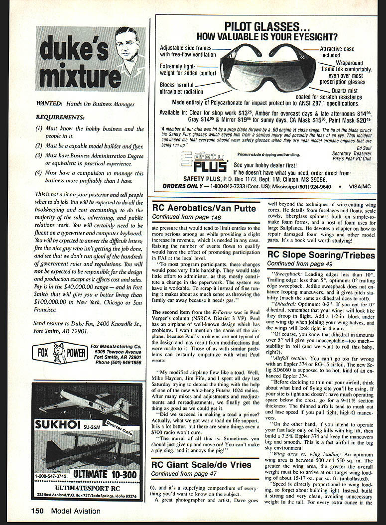
A while back the concept of variable‑sweep wings for slope ships was explored. Rich Spicer (an F3B expert from Northern California) built an experimental model with a swept, fully flying V‑tail (rudder‑vator). Key features:
- Model length: 42 in.
- Wing mount: shoulder mount with variable sweep.
- Span: ~60 in. fully forward, ~36 in. retracted.
- Purpose: change thickness‑to‑chord ratio rather than reduce frontal area. From the top view, the retracted planform resembled a delta wing.
- Wing movement was powered by a Futaba landing‑gear servo and was fully movable in flight.
- Flight stability during wing movement was maintained by two principles:
- The CG was variable with wing movement.
- The ailerons deflected slightly negative as the wings rotated rearward.
Rich’s work was an important first step. With today’s high‑strength, lightweight materials and advanced radios, further development of the swing‑wing Sloper is promising.
Swing-wings — Part II
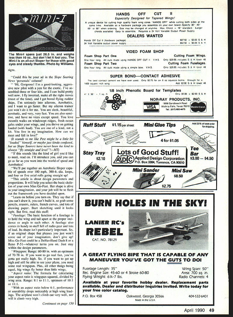
Bob Reynolds built an incredible F‑14B Super Tomcat with fully operational swing wings. Highlights:
- Based on a Jet Hanger ducted‑fan fuselage with larger flying surfaces.
- Fuselage: 1/6 scale; flying surfaces: 1/8 scale.
- Overall dimensions: about 80 in. long with a 94 in. span (≈8 ft.).
- Projected weight: 7.5 lb → wing loading ≈ 15.7 oz./sq. ft.
- Airfoils: Eppler 214 at the root, transitioning to Eppler 222 at the tip.
- Bob plans full swing‑wing operation like the real F‑14. The sight of the Tomcat sweeping its wings during a knife‑edge pass across a slope promises to be spectacular.
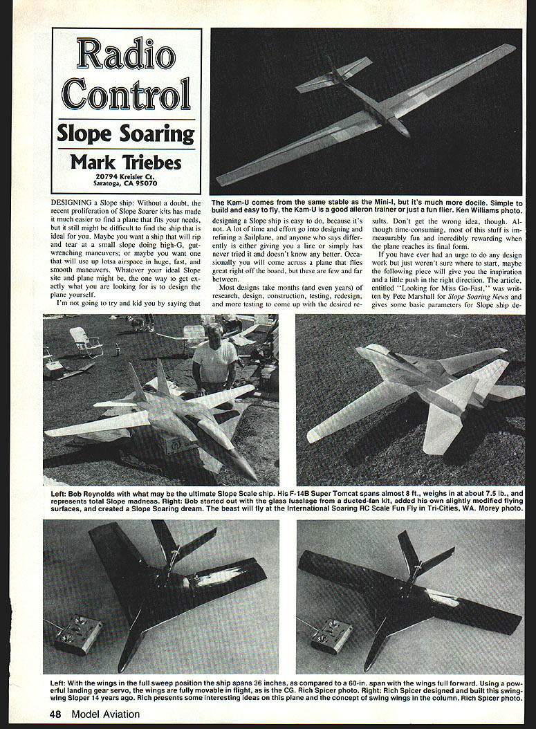
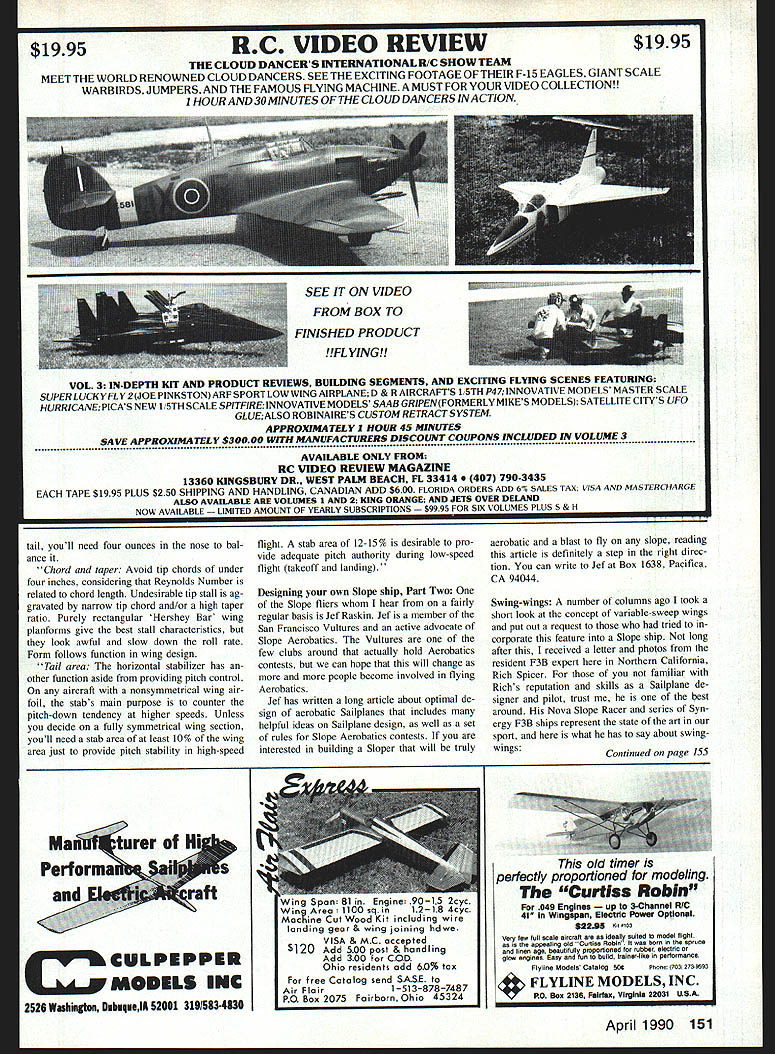
Mini‑I and Kam‑U
Small models have become popular as slope soaring grows. Two offerings from K&A Models:
- Mini‑I:
- Wingspan: 28.5 in.
- Area: 167.4 sq. in.
- Flying weight: 9.5–10 oz.
- Kit includes machine‑cut plywood and balsa parts, foam core wings, plans, instructions, and hardware.
- Requires a mini two‑channel radio and is aimed at experienced fliers.
- Needs quite a bit of wind to fly well and demands steady thumbs and good eyes — a quick, aerobatic ship for small slopes.
- Kam‑U:
- Wingspan: 50 in.
- Area: 287.5 sq. in.
- Flying weight: 19.5–20 oz.
- Kit is easy to assemble and of good quality; designed for a standard two‑channel radio.
- Designed for the intermediate flier: stable yet capable of aerobatics.
Transcribed from original scans by AI. Minor OCR errors may remain.

