
Radio Control: Soaring
Dan Pruss
Sagitta‑XC
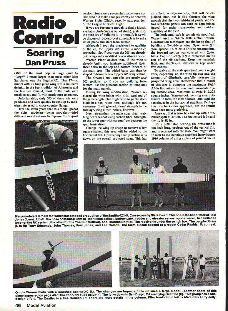
One of the most popular large (and by "large" I mean larger than most other kits) sailplanes was the Sagitta‑XC. This 174‑in. model with its four‑piece wing was a builder's delight. In the best tradition of Airtronics and its late Lee Renaud, most parts were machine‑cut and fit with nearly zero tolerance. Unfortunately, only 500 of these kits were produced and were quickly bought up by modelers interested in cross‑country flying.
Over the seven years that this model graced the skies, modelers—being modelers—tried different modifications to improve the original version. Some were successful; some were not. One who made changes worthy of note was Warren Plohr (Ohio), recently past‑president of the League of Silent Flight.
If you are fortunate enough to find a kit still available (Airtronics is out of stock), grab it for the pure joy of building it—or modify it as discussed here. Second‑best is to get a set of plans and start from scratch.
Although I tout the precision qualities of the kit, the Eppler 205 airfoil is modified somewhat. So, if you want the true 205, an already‑built wing can be modified or new ribs can be cut.
Wing modifications
Warren Plohr advises that, if the wing is already built, you laminate additional 3/32‑in. sheet balsa to the top and bottom forward of the main spar. The added balsa can then be shaped to form the true Eppler 205 wing section.
The plywood root‑cap ribs are nearly true 205 sections, so if you are building from scratch, use the plywood section as templates for the main panels.
During the wing modification, Warren replaced the wing joiner with a 1‑in. steel rod of the same length. One might wish to go the steel‑blade‑in‑a‑box route, although it's not necessary. It will give additional strength to the fuselage/wing attach points, however.
Next, strengthen the main spar shear webbing near the root using carbon fiber. Strengthen the lower spar with carbon fiber between the spar lamination.
Change the wing‑tip shape to remove a few square inches; this area will be added to the horizontal tail. Upsweeping the tip section cuts down the overall projected span. This has aerodynamic effects (explained below), but it also shortens the wing enough that the two right‑hand panels and the two left‑hand panels can be kept joined (taped) for easier transporting and quicker assembly at the field.
Horizontal stabilizer
The horizontal stab is completely modified. Warren used a NACA 0009 airfoil section. Construction techniques are similar to building a Two‑Meter wing.
- Spars: 3/16 x 3/8‑in. spruce.
- D‑tube construction: forward section covered with 1/16‑in. balsa.
- Cap strips: 1/8 x 1/16‑in. used on the rest of the rib sections.
- Keep materials light: the 39‑1/2‑in. stab can be kept under five ounces.
To arrive at the stab span (yours might vary depending on wing‑tip size and dihedral), carefully measure the projected wing area. Remember that a model this size is near the maximum AMA limitation for horizontal flying surface area. The maximum allowed is 2,325 square inches. Warren took the wing area, subtracted it from the maximum allowed, and used the remainder for the horizontal stabilizer. Perhaps this is a back‑door approach, but the results have been gratifying.
That is how he arrived at a stabilizer span of 39‑1/2 in. The root chord is 9‑1/4 in. and the tip is 4‑1/2 in.
For a better stab bearing, the brass tube is one inch long, projects out of the vertical fin, and is recessed into the stab. You might want to refer to the technique described in my March 1986 column using a piece of printed‑circuit board for the bearing.
Fuselage modifications
Fuselage modifications include splicing a 6‑1/4‑in. section aft for added longitudinal stability—good insurance when flying high and far away. The nose was lengthened 1‑1/4 in. to minimize the addition of lead ballast due to the longer tail moment arm. Whether the new fuselage sides are cut or the splice is made, the same height must be maintained front to rear as the original kit part.
The planform aft uses plywood sides with a straight‑line taper to the rudder post. The nose extension is formed from a block hollowed out to accommodate six ounces of lead shot mixed in epoxy. Space behind the nose block contains solid lead—the first bulkhead holds fourteen ounces—and behind that is space for the battery pack. A 12‑Ah Ni‑Cd pack was mounted.
Performance and availability
Is it all worth the effort? Consider this: the Ohio team, with Jim Bohmer at the sticks, set two course records of under 2‑1/2 hours over SOAR's Great Race course. That's 67 km (41 miles) of nonstop flying. Yet Skip Miller was the first in competition to finish the course using a stock Sagitta‑XC.
While talking to folks at Airtronics, they assured me there will be no return of the XC, but there is a good chance plans, a construction booklet, and the wing joiners will again be made available. That's good news for a lot of people.
Events and the F3B scene
I just received word from Warren Caldwell III (Corpus Christi, TX) that his club's second cross‑country meet will be held on August 23 and 24. That meet is unique in the support it receives from the U.S. Navy. Using a practice airfield that is shut down on weekends, the Navy gives them permission to use it on those days. Using the basic F3H rules, they fly on the field from which a five‑kilometer triangular course is laid out using the existing runways. Four times around gives a 20‑km course.
Driving the course is one step better than flying through sparse countryside, because the only vehicles on the road are the contestants. For more information, check the contest calendar in the "Competition Newsletter" section of Model Aviation.
From the F3B scene, there's at least one group taking the pre‑season seriously. With models a year or so old, they have been holding regimented practices in the San Diego area. The picture shows, left to right, Rick Schramm, Casey Goeller, Roger Roth, Larry Jolly, Steve Neu, and Dave Hice. Not in the picture is Koh Flinkenbeiner.
The planes are all Quattros, a product from Germany. Controls include ailerons and flaps which can be mixed to act as full‑span flaps or separately as flaps and ailerons. Wing construction includes foam, fiberglass, carbon fiber, and a mahogany veneer that warrants the wing a display in an art gallery. Workmanship is superb.
Remember that this is the year for the U.S. F3B team selection. Please support the program. Good lift.
Dan Pruss 131 E. Penington Ln. Plainfield, IL 60544
Transcribed from original scans by AI. Minor OCR errors may remain.

