
Radio Control: Soaring
Byron Blakeslee 3134 N. Whinebago Dr. Sedalia, CO 80135
THE ULTIMATE in the sailplaner's art is felt by many to be a craft made with modern all-glass technology and completely formed in molds. Fiberglass fuselages have long been made this way, but an all-glass ship has molded wings and tail surfaces as well. The top F3B planes built and flown by World Champions Rolf Decker and Reinhard Liese are made this way. Some commercially made sailplanes—Rowlings Impuls, Fiberglasflugels' Albatross, and some big scale sailplanes like the Roke DG-202—are molded glass. Not too surprisingly, all the planes named are made in Germany. The Europeans have been the leaders in this technology—both in full-size sailplanes and in models.
The U.S. needs to catch up in molded glass technology. For this reason I feel very fortunate to have received a step-by-step explanation of molding in glass from an expert: Martin Bamert. Martin is a Swiss citizen living temporarily in California.
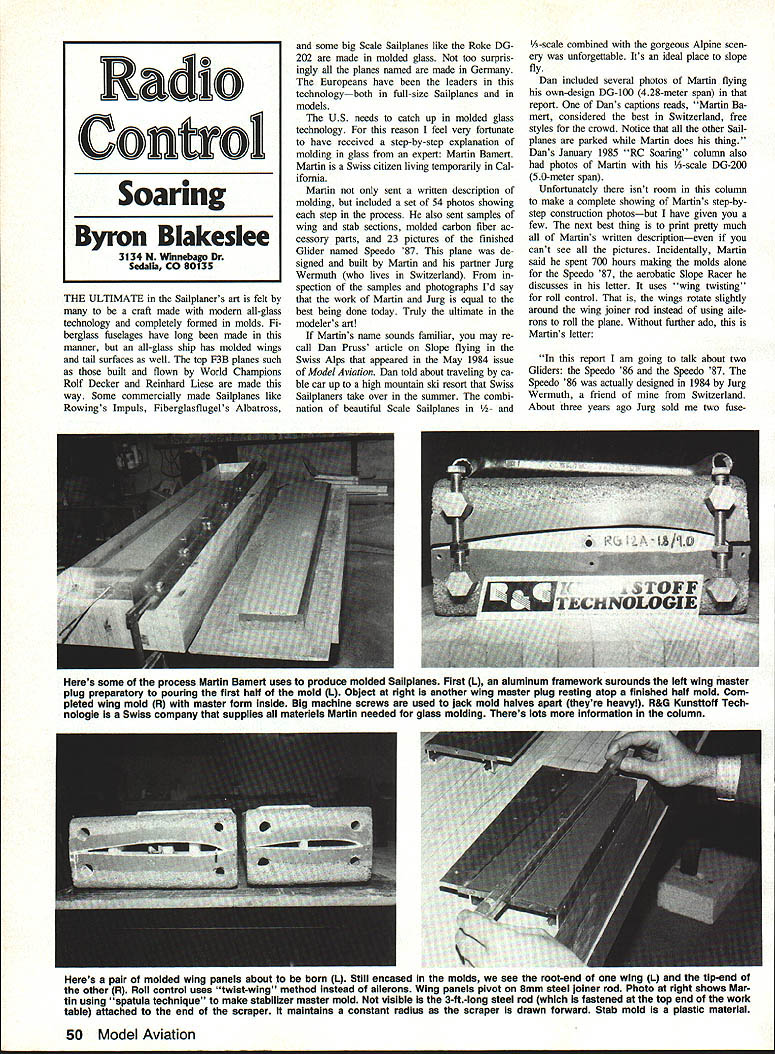
Martin not only sent a written description of molding, but included a set of 54 photos showing each step in the process. He also sent samples of wing and stab sections, molded carbon-fiber accessory parts, and 23 pictures of the finished glider named Speedo '87. This plane was designed and built by Martin and his partner Jürg Wermuth (who lives in Switzerland). From inspection of the samples and photographs I'd say the work of Martin and Jürg is equal to the best being done today—truly the ultimate in the modeler's art.
If Martin's name sounds familiar, you may recall Dan Pruss' article on slope flying in the Swiss Alps that appeared in the May 1984 issue of Model Aviation. Dan told about traveling by cable car up to a high mountain ski resort that Swiss sailplaners take over in the summer. The combination of beautiful scale sailplanes in 1/2- and 1/3-scale combined with the gorgeous Alpine scenery was unforgettable. It's an ideal place to slope fly.
Dan included several photos of Martin flying his own-design DG-100 (4.28-meter span) in that report. One of Dan's captions reads, "Martin Bamert, considered the best in Switzerland, free-styles for the crowd. Notice that all the other sailplanes are parked while Martin does his thing." Dan's January 1985 "RC Soaring" column also had photos of Martin with his 1/3-scale DG-200 (5.0-meter span).
Unfortunately there isn't room in this column to make a complete showing of Martin's step-by-step construction photos—but I have given you a few. The best thing is to print pretty much all of Martin's written description—even if you can't see the pictures. Incidentally, Martin said he spent 700 hours making molds alone for the Speedo '87, the aerobatic slope racer he discusses in his letter. It uses "wing twisting" for roll control. That is, the wings rotate slightly around the wing joiner rod instead of using ailerons. Roll control—without further ado, this is Martin's letter.
Martin Bamert — Speedo '86 and Speedo '87
Introduction
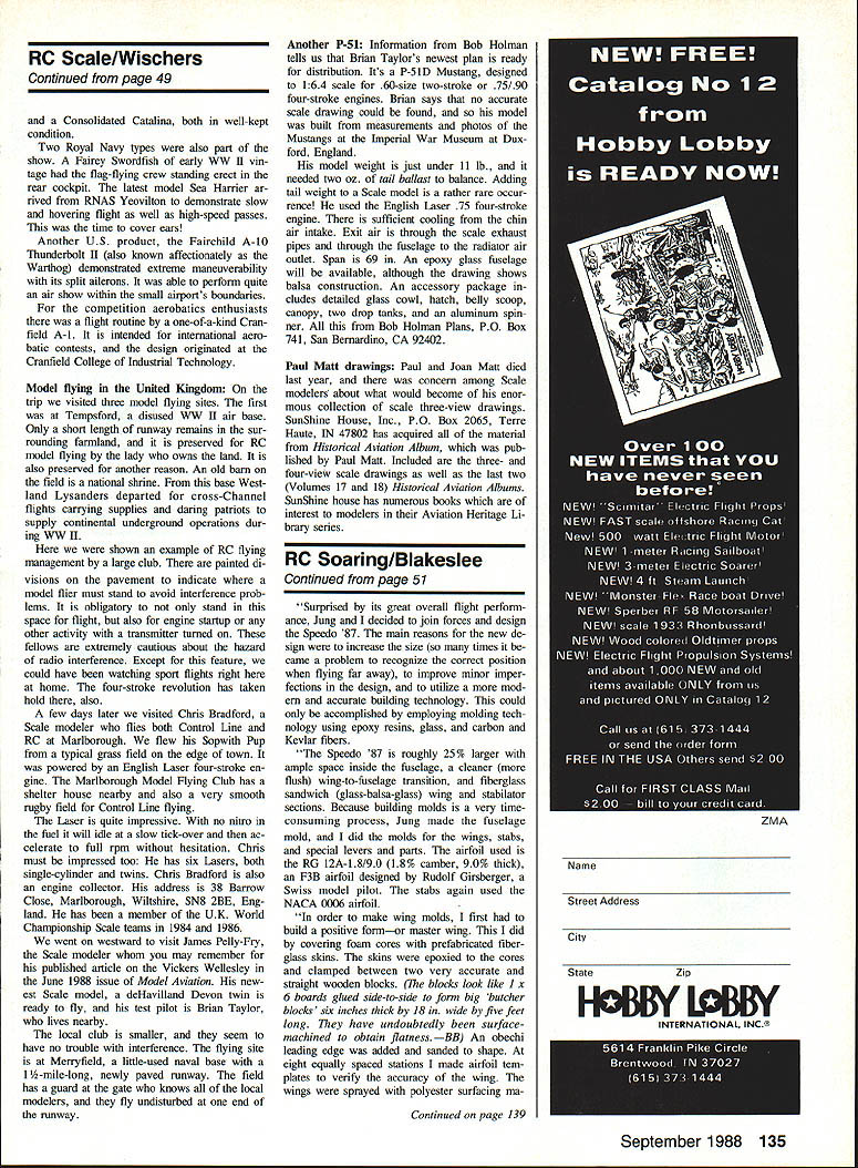
In this report I will talk about two gliders: the Speedo '86 and the Speedo '87. The Speedo '86 was actually designed in 1984 by Jürg Wermuth. With his valuable hints I built two of these models. Building a model like that is not exactly an easy task. Because of its relatively small span (78 in.), the whole model had to be built very accurately in order to achieve an acceptable level of performance.
Speedo '86
The glass fuselage (without white gel coat) was reinforced with plenty of carbon fiber and Kevlar. The wings were built in foam/glass and sheeted with obeche wood. The glass cloth was laid diagonally over the foam cores for increased torsional strength (very important for high-speed flights). It uses a JW airfoil (designed by Jürg) which is 10% thick and slightly undercambered approaching the trailing edge.
The rudder and stabilizers were cut from a piece of balsa. Stab airfoil was roughly a NACA 0006 (fully symmetrical). Wing, stabs, and rudder were covered with a white polyester iron-on film which gives the model its final touch. RC controls are elevons, spoilers, elevator, and rudder. Building the controls created some problems because space was very limited in the fuselage. Even though I love working with tweezers, I was finally happy to have completed installing the three servos, receiver, and batteries.
The first flights exceeded my expectations. I flew in a slight upwind when even the lightest gliders were fighting to stay in the air. With a wing loading of 15.1 oz. per sq. ft., that is quite an accomplishment. The model also responded very well to thermals and easily climbed to heights where I had difficulty recognizing it.
The Speedo '86 is completely aerobatic and is at its element when diving 600 to 800 ft. straight down. Nothing rattles or shakes, and it behaves fairly predictably through high-speed flight. Most of the kinetic energy can then be converted back into height. The model has been clocked at over 100 mph. I have flown my Speedo '86 over 120 hours and have never crashed it. Every slope I take it to results in its attracting curious and inquisitive model pilots.
Speedo '87 — reasons for redesign
Surprised by the great overall flight performance of the Speedo '86, Jürg and I decided to join forces and design the Speedo '87. The main reasons for the new design were:
- increase size (to make position recognition easier at distance),
- improve minor imperfections in the design,
- utilize more modern and accurate building technology.
This could only be accomplished by employing molded techniques using epoxy resins, glass, carbon, and Kevlar fibers.
The Speedo '87 is roughly 25% larger with ample space inside the fuselage, a cleaner (more flush) wing-to-fuselage transition, and fiberglass sandwich (glass-balsa-glass) wing and stabilator sections. Because building molds is very time-consuming, Jürg made the fuselage mold and I did the molds for the wings, stabs, and special fixtures and parts.
The airfoil used is the RGA 12A-19/8.0 (1.8% camber, 9.0% thick), a 7.5% airfoil designed by Rudolf Girsberger, a Swiss modeler. The fuselage is 3/8-oz. glass with a 1/16-oz. outer skin. The stab sections were glass-balsa-glass and cored with 1/8-inch balsa.
Molding process (overview)
To make wing molds I first built a positive form—master wings—by covering foam cores with pre-bonded fiberglass skins. The skins were epoxy-patched and clamped between two very accurate and perfectly straight wooden blocks (the blocks looked like 1 x 6 boards glued side-to-side to form big "butcher blocks" about six inches thick by 18 inches wide by five feet long). The molds were then surface-machined to obtain flatness.
Key steps:
- Shape an obeche leading edge to a 1/8-inch radius; glue the wing cores onto it and add balsa to verify accuracy.
- Spray the wings with polyester surfacing material and sand to eliminate imperfections.
- Place one master wing inside an aluminum frame and coat with gray molding resin; add a thin glass layer.
- Fill the frame with a mixture of resin and quartz sand for stability; fit steel tubes to hold the mold together.
- Build the upper half of the mold on top of the lower half; repeat for the other wing (molds for one wing weigh about 120 lb).
- Polish the finished molds and treat with a releasing agent.
- Spray a white gel coat into the molds, then add 40 g/m² glass cloth soaked with epoxy resin.
- Place a 1/8" balsa skin on the soaked glass cloth, bag in polyethylene and vacuum for 24 hours.
- After removal from the bag, add another layer of 120 g/m² glass cloth plus reinforcements and glue spars in place.
- Trim edges carefully and glue wing halves together with epoxy, clamping leading-edge-downward to form internal fillets.
Notes on spars and construction:
- Sub-spars were cut from blue foam while main spars consisted of balsa and carbon fibers.
- There is room behind the main spars for additional ballast weights.
- Main spar construction is complex because the airfoil thickness at the root is only 20 mm and dihedral is built in (total dihedral 5.5°).
- Molds were designed to make wings up to 2.63 meters span; we trimmed molded wings to the required size and are experimenting with different tip shapes.
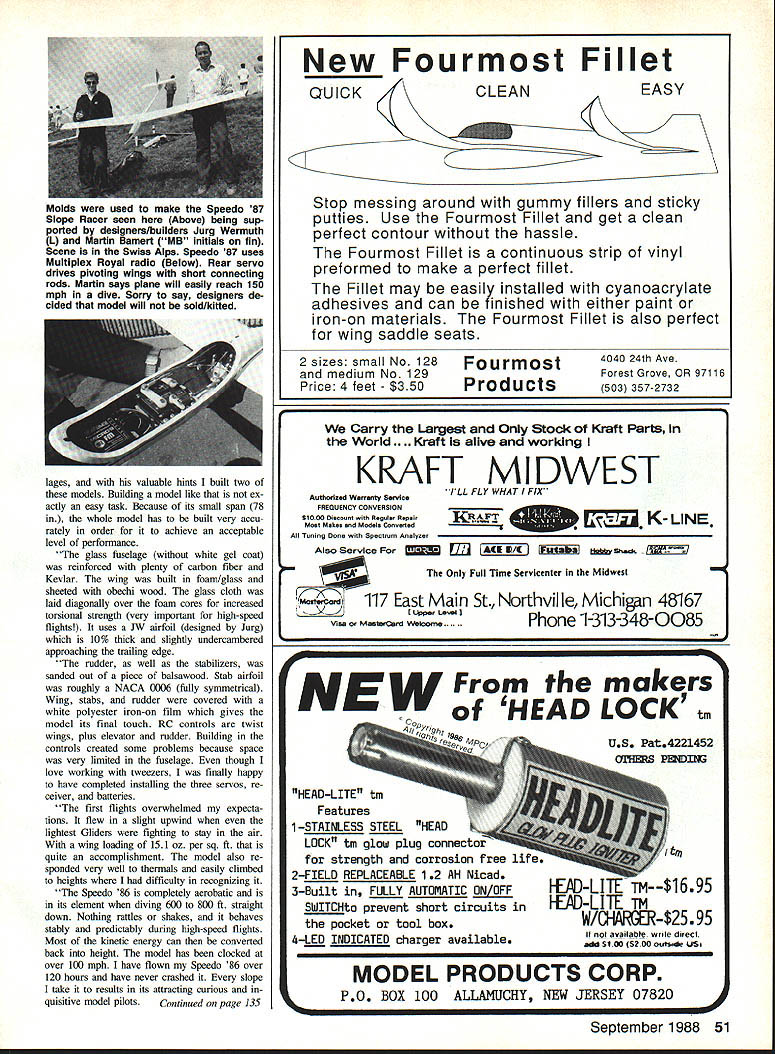
Stabilator (spatula technique)
The positive form for the stabilators was made differently to achieve greater accuracy at the leading and trailing edges. The "spatula technique" starts with a very sturdy aluminum base plate the exact length of the stab or wing. Airfoil templates are screwed to each end showing exactly half the airfoil above the base plate. The space between the templates and the base plate is filled with gray molding resin, then with a straight ruler the resin is drawn forward from the trailing edge to the leading edge repeatedly (up to 20 times) to achieve a precise contour.
After curing and removal of the templates, an aluminum frame is built around the base plate and the molding process proceeds much like the wing molds. Because the stabs are symmetrical, only an upper and lower section of one part were needed. The balsawood used for the stab sandwich is 1/2" thick.
Fuselage and special parts
Jürg made the fuselage mold. The top coat is a white gel coat (40 g/m²). Kevlar cloth was used in parts; Kevlar is about one-third lighter than glass but is very difficult to trim. Graphite (carbon) fiber strands were also inserted where needed.
The carbon fibers added in the skinny tail section of the fuselage are necessary for high-speed flight. At high speed models tend to pitch down; the stabilizers must exert a downward force to maintain level flight. If the fuselage isn't stiff enough it will bend, making control difficult. To make one fuselage takes about eight hours.
Special parts for the Speedos were made in molded carbon fiber. These include the stab crank lever (which incorporates two ball bearings). The wing joiner rod is 8 mm steel; roller bearings ensure easy rotation of the wing panels. Early Speedo '87 models had their wings twisted by small crank levers; currently we drive the leading edge pins directly from a Multiplex servo. I have used a Multiplex Royal radio for years and am very satisfied with it.
Flight impressions and conclusion
I was not overly worried before the maiden flight of the Speedo '87, but after investing about 800 hours of work (I worked on this project for three months straight without a regular job) I wondered what would happen. It flew beautifully without major adjustments. After the first few turns I noticed slight snap rolls during inverted flight. I could hardly stall it, and when it did stall it went into a smooth downward curve. Its ability to recover speed into height surprised me; it was much better than the Speedo '86.
Because of its low-speed capability I can take advantage of even the smallest thermals. With its 9% airfoil it is also a very fast glider; speeds up to 150 mph are easily reached. Due to its high penetration the Speedo '87 is also perfect for aerobatics—loops and snap rolls at high speed are easy. After about the first two hours of intensive flying I could see it easily outperformed its smaller brother. Time after time the Speedo '87 has been admired by amazed glider pilots; I can say without bragging that it pretty much outperforms every glider I have owned in 17 years of flying.
I hope you can see that with the kind of handcrafting involved you can't mass-produce or get a realistic price tag on this model. For these reasons Jürg and I have agreed not to sell the Speedo '87.
Thanks very much to Martin Bamert for taking the time to share his important and interesting technology. I hope this description will encourage some Americans to try to duplicate it.
F3B in Britain
A recent issue of Sean Whelan's White Sheet Club newsletter contained a very interesting article by Bill and Stephen Haley on their latest F3B design, the K.B. Merlin. Stephen flew his Merlin to a very creditable fourth place in the 1987 World Championships. Bill was the British team manager, and they came within a few points of repeating the World Champions—just getting nipped at the wire by the Austrians.
Sean, who also edits the "Soaring" column in R/C Model World magazine, is well-known for producing the "inside scoop" from model design circles. Here is Bill Haley's account of the development of the K.B. Merlin:
Development background
When asked to give the story of the development of the K.B. Merlin, flown by son Stephen into fourth place in the 1987 World Champs in West Germany, my first reaction was, "How far do I go back in history?" Most competition model designers would agree that good models are developed over a long period through a series of models, each usually a modified version of the one before. Ours are no exception, but with the K.B. Merlin we made some rather drastic changes from our previous F3B models.
The obvious starting point was the demise of our beloved Eppler 193 airfoil, changing to a Quabeck section for the World Champs team trials which were expected to take place in late 1986. We believe the 193 is one of the finest all-round sections available for soaring—indeed I placed fourth in two previous team trials using this section. However, the 193 was not fast enough for modern international competition.
We built a pair of F3B models using the Quabeck 2.10 section (2% camber, 10% thick). These models had a span of 116 in., straight-tapered from a nine-inch root to a seven-inch tip chord. They had plug-on wings incorporating ballast tubes as the wing-joiner tubes, with a 7/8-in. titanium bar for the joiner.
In an effort to save weight we eliminated the spar and used HT alloy tube as the spar, reinforced with carbon on top and bottom. These wings were covered with epoxy/glass skins made on sheet glass and attached using epoxy and the vacuum-bag system. The models incorporated full-span flaperons operated by two servos in each wing.
The spar idea turned out better in theory than in practice. A crash at the '86 nationals split the carbon fiber away from the alloy tube on Stephen's model, and a later crash with mine did the same—the bond between the tube and the carbon fiber wasn't good. Perhaps the tube preparation was inadequate. Although the models were very fast, we found Duration and thermalling much harder; thermal turns posed particular problems.
Rethink and new direction
Having been to both European and World Championships with the British team, I am convinced that British fliers are the best thermal pilots in the world. Our ambition was to build something faster but still with good lift performance. We set simple performance criteria for a new wing: capable of eight minutes every flight, averaging 24 laps in Distance, and an easy 16 seconds in Speed every time, even in down-thermals.
We came across the Gittsberger sections and decided the RG 15 looked promising. Naively we thought we had discovered a new section no one else was using—little did we know!
With the decision to build completely new models in the short time available, we built two models each for the trials. The new wings were again on blue foam cores but with composite carbon-fiber spars this time. They were covered with epoxy/glass skins and built as one-piece wings for better torsional rigidity. Ballast tubes were incorporated in the wing tips. Wings were built using a vacuum-bag technique with small hatches in the top. The wing is one-piece except for plug-on tips to allow carrying in a 10-ft model box.
Plug-on tips proved to be a mixed blessing: crash repairs were easier and aileron adjustments simpler, but they introduced other issues. We also used a spring-loaded skid projecting below the fuselage to protect the propeller in a heavy landing and a fixed rear skid to support the tail.
Trials and conclusions
The trials were hard with trying weather, particularly for the Duration tasks. We learned much about wing layup, ballast, and section selection to get the right combination of speed and thermal performance.
We are delighted with the results and are already working on '88 models. We learned a great deal in '87 and feel our models can be improved further. Our only regret is that more people don't try F3B and experience the thrill of piloting a beautifully handling plane in the various tasks.
It is our belief that F3B is the "Formula One" of soaring. We hope a few people will try the Sportsman Task/F3B League introduced in 1988. It is amazing that with so few dedicated F3B fliers in this country (Great Britain) we do as well as we do internationally. With more support we would do even better—so come on all you budding World Champs: have a go.
Thanks to Bill and Stephen Haley for sharing these thoughts, and to Sean Walbank for his newsletter.
ULF-1 plans
My article on the Wasserkuppe that appeared in the May issue had photos of an unusual glider known as the "Ultra Light Footlaunch-One" (ULF-1). Several readers requested plans and more information. M&A's publisher, Carl Wheeley, located the source:
- Dieter Reich, Heiner Neumann
Aero-Bau, Strasse No. 16, D-8000 Munchen 82, West Germany.
The ULF-1 plan pack consists of 30 blueprints, cutaway drawings, and instructions in English. The 1986 price was 36.00 Deutsch Marks (about $21 at current exchange rates). Carl reminded potential builders that foot-launch gliders are as unforgiving to life and limb as any other aircraft; anyone attempting to fly one should have prior instruction and training in conventional slope sailplanes.
1988 MARCS Sailplane Symposium
Chairman Bill Vosselgang announces the 1988 MARCS Sailplane Symposium will be held November 12–13, 1988, in Madison, WI. The format will be similar to previous years with talks, table clinics, etc. For those arriving early, a trip to the EAA Museum in Oshkosh will be arranged.
This fall get-together is becoming a "must" for Sailplaners in the Midwest and others who can fly in for the weekend. Further information may be requested from:
- Bill Vosselgang
5933 Mayhill Dr., Madison, WI 53711
Slope Soaring news
Model Aviation's new "Slope Soaring" column, edited by Mark Triebes, is a first for American magazines and a sign of progress in spreading the gospel of slope flying. For the most part I will concentrate on flatland soaring and defer to Mark on slope matters, with occasional exceptions for special events.
One such exception was the Scale Slope Fun-Fly held in Richland, WA over the Labor Day weekend. Contest Director Bob Vesper hosted the event and had over 30 entries during the two-day affair. The event featured both regular sailplanes and power scale ships. Many people came just to spectate and talk scale sailplanes. There were 124 at the Saturday evening banquet.
Support from model manufacturers and dealers was excellent; they contributed over $4,000 worth of merchandise. There were top awards and scale kits; every flier received some prize. We'll send a complete report with pictures in a future column.
The seminar was topped off by District IX Radio Frequency Coordinator Steve Mangels, who presented facts about narrow-band and broadband transmitters and receivers. There is a lot to recommend following Chapter 90's lead in scheduling such a "super show-and-tell"—a fine example of modelers helping modelers.
Our club has voted to certify all RC transmitters. At our May meeting there was a certification "orgy"—over 200 transmitters were checked and stickered. Although it isn't an AMA requirement, flying at the club field should now be much safer electronically. This, combined with six carefully spaced concrete-block pilot positions, should minimize radio interference accidents. Now, if we can only convince people not to turn on unless they have the pin...
Transcribed from original scans by AI. Minor OCR errors may remain.

