
Radio Control: Soaring
Byron Blakeslee 3134 N. Winnebago Dr. Sedalia, CO 80135
MAYBE this column will come out a little uneven, because I'm watching the Olympics while trying to type. Wouldn't it be great if RC soaring were an Olympic event? There's nothing like world-class competition to get the old juices flowing! Only a few sailplane pilots get the privilege of flying in international competition, but most of us can sample the "rush" by flying in local club contests. Hope you try it — you'll like it!
ATRCS radio news
The August 1988 column described the ATRCS (pronounced "A-Tracks") microprocessor conversion for the Airtronics Module 75P transmitter. Last month Asher Carmichael told us how pleased he was with his ATRCS set. Gene Englegau and Tom Mroz of Control Systems Laboratories (CSL) developed ATRCS (Advanced Technology Radio Control System) to give us the exotic mixing features of European radios at a more reasonable price.
Six contestants at the F3B team-selection finals used Airtronics Module/ATRCS radios, and they were emphatic about how happy they were with them (six in addition to Gene, who was a finalist). Gene, being a topnotch sailplaner, designed in all the features you'll likely ever need for flying gliders — including flying-wing types.
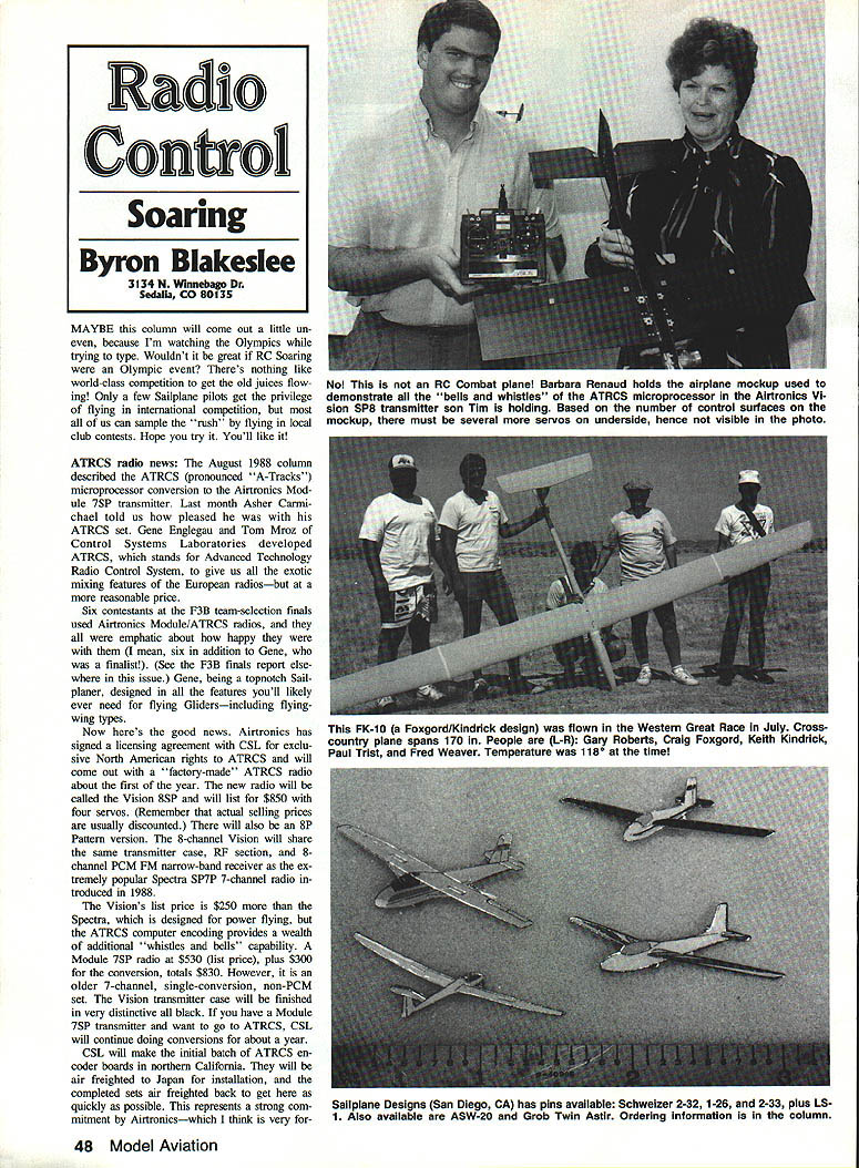
Good news: Airtronics has signed a licensing agreement with CSL for exclusive North American rights to ATRCS and will release a factory-made ATRCS radio around the first of the year. The new radio will be called the Vision 8SP and will list for $850 with four servos (actual selling prices are usually discounted). There will also be an 8P Pattern version. The 8-channel Vision will share the same transmitter case, RF section, and narrow-band PCM FM 8-channel receiver as the popular Spectra SP7P 7-channel radio introduced in 1988.
A Module 75P radio (list $530) plus a $300 ATRCS conversion would total about $830, but the converted set is an older 7-channel, single-conversion, non-PCM design. CSL will continue doing conversions for about a year. CSL will make the initial batch of ATRCS encoder boards in northern California, air-freight them to Japan for installation in the Airtronics factory, and air-freight completed sets back to North America to get them to market quickly. This represents a strong commitment by Airtronics — important for sailplaners. Airtronics' founder, Lee Renaud, was a sailplaner himself, and the company retains a strong interest in our part of the hobby.
I have a hunch the Vision will become the radio for serious sailplaners because of its reasonable price and tremendous versatility. Simple rudder-and-elevator gliders don't need it, but computer encoding is the way to go if your plane uses four or more channels. After a period of time I think the Vision will help boost interest in F3B flying because it has all the required features and greatly eases the setting up of mixing, camber-changing, crow, landing, etc.
ATRCS — abbreviated feature rundown
- Stores full setups for up to four planes.
- Has seven "type-of-plane" templates (including two flying wings) which specify number of servos and what each servo controls. Templates preprogram the computer to configure the transmitter for each plane so you don't have to start from scratch.
- Receiver selection from the keyboard, including Airtronics and Futaba types.
- Trim, travel adjustment, and reversing on all eight channels.
- Provides all required mixing plus aileron differential and crow. Mixing is done within the computer and the LCD shows mix as a percentage of full travel. No pots or reversing switches are used.
- Three-position switch selects preset wing camber settings for launch, cruise, and speed (reflex).
- PCM failsafe feature can be used or disabled.
When you get one, try playing with the computer program. It's very similar to popular computer spreadsheets (like Lotus 1-2-3) with columns and rows. There are five columns: Main menu, Basic configuration, Surface adjustment, Mixer gains, and Presets/Dual-rates. There are up to 12 rows where you set various adjustments. It's not difficult, and it's quite a bit of fun.
Target tow (procedures and mechanisms)
If you're interested in target-tow operations, here is a basic outline of the flying sequence and the tow mechanism considerations.
- Flight sequence:
- Three sequential passes in front of the flight judges are required.
- The target sleeve is usually carried internally in the aircraft or within an externally mounted pod. The sleeve is typically 1/2 to 1/3 the length of the aircraft and should be towed at a distance of about 10 to 20 times the length of the towing aircraft.
- After deploying the sleeve while flying at cruise speed and minimum altitude, make a straight flyby at low altitude (about 50 to 60 ft.) to simulate a ground-to-air gunnery training run.
- Then make a low-altitude pass (10 to 20 ft.) into the wind and parallel to the runway just beyond the landing area. Drop the target sleeve and towing cable here. Calling the drop and performing it just as the model passes in front of the judges makes a good impression.
- Safety note: Do not drop the sleeve and line onto the runway — the 50–75 ft. of tow cord can get entangled in the prop of a landing model (usually the tow model). That can be a real mess.
- Basic requirements for a tow mechanism:
- Hold the folded sleeve and the reel of tow cord securely until released.
- On command, eject the sleeve and unreel the full length of tow cord.
- On command, release the tow cord from the reel.
There are many ways to accomplish these items. The author describes his Swiss target-tow model, the C-3506 Schleppt, which uses one servo for all tow functions. By trial and error he learned several helpful points:
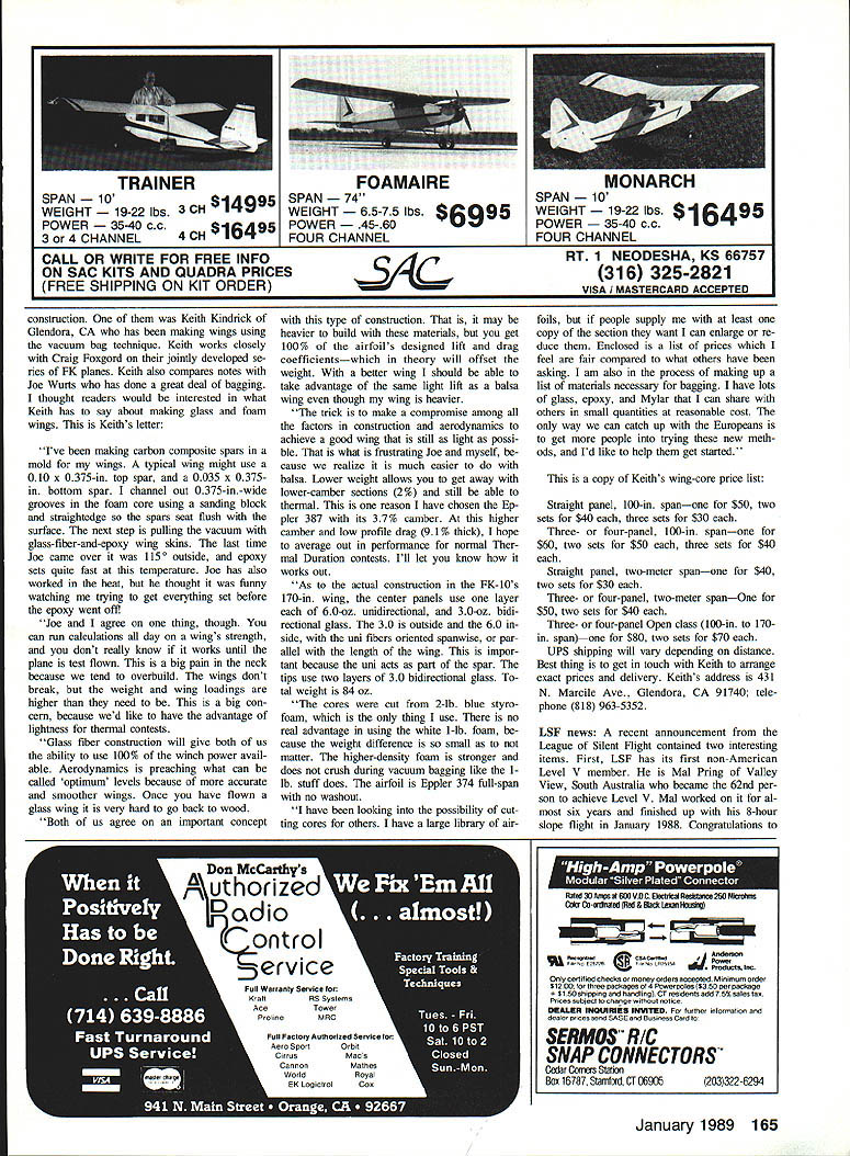
- Sleeve material is important. You want a lightweight, very springy material that compresses into a small space (about 1 x 2 x 3 in.) and will spring out to its tubular shape when released. The material should be moisture-resistant.
- Silk worked when perfectly dry but became soggy in drizzle. Sig's Koverall polyester covering material worked; lightweight Dacron (sailmaker's spinnaker fabric) would be ideal. Full-size Schlepp sleeves use Dayglo red or orange.
- The reel spool can be built from hard balsa and 1/16" plywood and made removable as a unit (servo and all).
- The tow servo can be operated off an auxiliary channel. Place the auxiliary lever center for takeoff, up to deploy the sleeve, and down to drop the sleeve and tow cord.
- A small electric motor geared to the spool can serve two purposes:
- When shorted across its brushes it acts as an electrical brake during deployment to prevent overspeed and tangling.
- When the shorting plug is removed and a small Ni-Cd cell connected, the motor slowly rewinds the tow cord after the flight — convenient for rewinding 50 ft. of Dacron tow cord.
If you'd like to try something more fun and challenging than a usual bomb or belly-tank drop, try the target tow option.
Materials and construction tips (tow & sleeves)
- Use lightweight, springy, moisture-resistant fabric for sleeves (Dacron/spinnaker cloth recommended).
- Build the reel to be removable and serviceable.
- Employ braking (electrical or mechanical) to control reel speed during deployment.
- Consider using an auxiliary transmitter channel to sequence deploy/hold/release.
Glass and foam wings — Keith Kindrick (Glendora, CA)
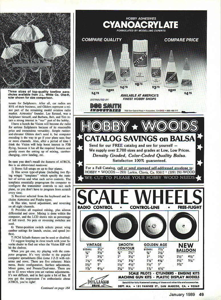
One of the emerging construction techniques is vacuum-bagged glass and foam wings. Keith Kindrick of Glendora has been making wings using vacuum bagging and works closely with Craig Foxgord on FK-series planes. Keith also compares notes with Joe Wurts. Below are Keith's observations and construction details (edited for clarity):
- Spars and core: Typical wing uses a top spar about 0.10 x 0.375 in. and a bottom spar about 0.035 x 0.375 in. A 0.375-in.-wide groove is channeled in the foam core so spars seat flush.
- Vacuum-bagging: Glass-fiber-and-epoxy wing skins are vacuum-bagged. Epoxy sets faster in heat — Keith recalls trying to work at 115°F!
- Flight testing: Calculations are helpful, but the real test is a flight — the only sure way to know is to fly (and sometimes break).
- Performance: Glass-fiber construction yields very accurate, smooth wings. Once you fly a glass wing it's hard to go back to wood. Although composite wings may be heavier, they can deliver 100% of the airfoil's designed lift and drag coefficients, which can offset the weight penalty.
- Airfoil choice: Keith has chosen the Eppler 387 (3.7% camber, 0.9% thickness) to aim for good thermal performance despite higher wing weight.
- Materials in FK-10 170-in. wing:
- Center panels: one layer of 6.0-oz. unidirectional and one layer of 3.0-oz. bidirectional glass. The 3.0 is outside; the 6.0 inside. Uni fibers run spanwise and act as part of the spar.
- Tips: two layers of 3.0 bi-directional glass.
- Total wing weight: 84 oz.
- Cores: Cut from 2-lb. blue styrofoam (preferred over white 1-lb. foam because the higher-density foam resists crushing during vacuum bagging).
- Service offer: Keith can cut cores for others and has a large library of airfoils. If you supply a section, he can resize it. He also offers small quantities of glass, epoxy, and Mylar at reasonable cost to help others get started.
Keith's address and phone: 431 N. Marcile Ave., Glendora, CA 91740 Telephone: (818) 963-5352
Keith's wing-core price list:
- Straight panel, 100-in. span:
- One: $50
- Two sets: $40 each
- Three sets: $30 each
- Three- or four-panel, 100-in. span:
- One: $60
- Two sets: $50 each
- Three sets: $40 each
- Straight panel, two-meter span:
- One: $40
- Two sets: $30 each
- Three- or four-panel, two-meter span:
- One: $50
- Two sets: $40 each
- Three- or four-panel canards (100-in. to 170-in. span):
- One: $80
- Two sets: $70 each
UPS shipping will vary. Contact Keith to arrange exact prices and delivery.
LSF news
The League of Silent Flight announced two interesting items:
- Its first non-American Level V member: Mal Pring of Valley View, South Australia, became the 62nd person to achieve Level V after nearly six years' effort and finishing with an 8-hour slope flight in January 1988. Congratulations to Mal.
- The first "Double Level V": Bob Champine (Newport News, VA) completed his Level V some time ago and, with LSF permission, started over and completed a second Level V (No. 2) in August 1988. He began the second effort in January 1985 and finished in August 1988. Bob is to be congratulated for accomplishing something twice that most of us can't do even once.
Competition Products foam wings — Ed Berton
Ed Berton continues his discussion of foam wing cores and full-size construction saddles, focusing this month on using epoxy to attach balsa skins to foam cores. Key points from Ed:
- Adhesives: He previously used 3M No. 77 spray adhesive; it's strong but alignment is difficult because it's essentially permanent once applied. On his current wings he used a very thin epoxy (Windsong brand, mixed 3:1) labeled 204LV from Fiberglass Coatings — about $8/qt. He used roughly 1.75 oz per skin (about 5 oz total for both wings).
- Application technique:
- Apply epoxy to one-piece skins with a 3-in. square piece of 1/4" plywood as a squeegee to make a very even thin coat. This thin coat begins to soak into the balsa.
- Apply epoxy to the leading and trailing edges of the core in a swath about 3/4 in. wide.
- Use a 3-in. foam paint roller to go over the skin before applying it to the core. You can add epoxy to the skin as you roll or fill the roller with epoxy. This is important because:
- The thin epoxy applied with the plywood is absorbed into the balsa — if you apply the skin to the core too soon, you may get areas of poor or no bonding.
- A brush can apply epoxy unevenly or too thickly.
- The foam roller allows the initial thin epoxy to soak into the skin and the epoxy applied with the roller to remain raised, producing a good bond to the core.
- Joining skins: Sig-Bond aliphatic resin glue is recommended for joining balsa sheets into one-piece skins — strong and inconspicuous after covering.
Competition Products can cut foam cores up to 72 in. long. Contact Ed for cores: 921 Birdie Way, Apollo Beach, FL 33570 Phone: (813) 645-5171
Trimming and stability (from "Pilot's Logbook" — Patrick Kelly)
A helpful article on glider trimming explains why moving the center of gravity (CG) should primarily be used to change stability, not to set trim for level flight.
- Primary reason for CG placement: to control pitch stability. The CG is normally ahead of the wing's center of pressure (CP) and is balanced by downward lift from the horizontal stabilizer. The CG moment and the stabilizer downforce must balance around the lift point for level flight.
- Effects of CG position:
- Move the CG farther forward of the CP: greater restoring moment, more control force required to change pitch, aircraft becomes more stable (less sensitive).
- Move the CG aft: aircraft becomes less stable and more sensitive; if too far aft the aircraft may be unstable and difficult or impossible to trim for level flight.
- Proper procedure: Set the CG for the desired stability and then use elevator trim to establish the desired flight attitude (angle of attack) for level flight. Use small trim adjustments for fine-tuning.
- Static vs. dynamic stability:
- Static stability: initial reaction after a control input. If you raise the nose and release the elevator:
- A statically stable plane: nose should drop back toward the original attitude.
- Neutral stability: nose remains where left.
- Unstable: nose continues to rise (or diverge).
- Dynamic stability: behavior of oscillations over time. For a statically stable plane, the oscillations can damp out (dynamically stable), persist (neutral), or grow (dynamically unstable).
- Practical test: A shallow dive is a revealing maneuver. A stable plane will raise its nose after releasing down trim; an unstable plane will tuck and dive.
Hopefully this helps you trim your plane better. Deciding how much stability you want is part of the fun.
Richland Scale Soaring Fun-Fly correction and preview
A correction: The October column included photos from the First Annual Scale Soaring Fun-Fly. The SG-38 Primary Glider photo was identified as Tony Palluttiero's when it was actually Erik Eiche's (Vancouver, BC). Erik has been ill; he thanked friends for get-well wishes and expects to be back for the first contest of the '89 flying season. Good going, Erik!
Advance notice for the 1989 Scale Soar Fun-Fly: Will Bryn says they are planning four days and hope to attract more foreign flyers, making it a truly international event. Scale enthusiasts should plan to spend the end of May in Washington State.
Transcribed from original scans by AI. Minor OCR errors may remain.

