
Radio Control: Soaring
Byron Blakeslee 3134 N. Winnebago Dr. Sedalia, CO 80135
New Bird
This month's column is a bit unusual because about 80% of it is devoted to a single item — Frank Weston's description of the design and construction of a large Terminator Unlimited-class sailplane. Frank lives in Arnold, MD, and is a member of the Capital Area Soaring Association (CASA). When I first read Frank's article in CASA Comments (edited by Gus Peleuses), it struck me as significant and worth sharing with all sailplaners. Frank is a trained aeronautical engineer who takes you step by step through his thought process and balances technical design with practical construction decisions.
A major choice in the Terminator project was to use modern composite construction and vacuum-bagged wings. Even if you prefer balsa and spruce, Frank's description of these newer techniques — which let you build truer, stronger wings much faster — is worth reading. Now, over to Frank Weston.
Terminator — What is it?
By Frank Weston
Terminator is the result of ideas I’d been developing for about a year. I wanted to use modern materials and methods to build a sailplane that significantly exceeds the performance of current designs. “Performance” meant: high L/D, excellent control for landings and descents, high durability, and low minimum flying speed.
During development I tried many ideas. Some worked, some didn’t. The ones that worked were kept; the others I gave to my friend and competitor Jack Cash.
Some of the main ideas included:
- Big is better to a point — bigger size gives better Reynolds numbers, better visibility at distance, and more stable handling. Downside: too big can mean poor launches and more damage on landing.
- High aspect ratio and a T-tail are better — these increase efficiency and L/D but can produce a more fragile structure and require stiffness to avoid bad behavior at high speed.
- Use a good airfoil — the Princeton tests (Selig, Donovan, Fraser — Soartech #8) provide data that help pick the right airfoil.
- Counter the downsides of size and aspect ratio (high weight, fragility, lack of rigidity) by using new construction materials and methods.
- Design it pretty — form follows function with sailplanes; it’s hard to design an ugly one.
With those goals, I defined my external constraints:
- Length of my car cargo area: 83 in.
- Length of my basement workshop: 16 ft.
- Weight a standard ESL winch can handle: about 7 lb.
- Maximum foam panel length I can cut accurately: 40 in.
- Time and money I could afford.
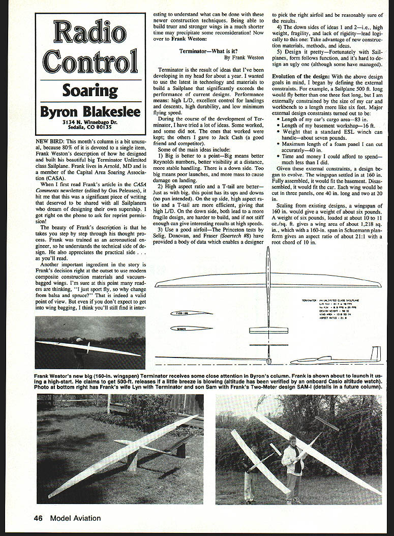
Given these constraints, the design evolved. Wingspan settled at 160 in so the assembled plane would fit the basement and, disassembled, the car. Each wing would be cut into three panels (one 40 in. panel and two 20 in. panels). Scaling from existing designs suggested a weight around 6 lb. At about 10–11 oz/sq ft wing loading, that implies a wing area near 1,218 sq in. A 160-in Schuemann planform gives an aspect ratio of about 21:1 with a root chord near 10 in.
Why 10–11 oz/sq ft wing loading? Larger, faster planes need more wing loading. Hand-launchers fly near 4 oz/sq ft, Two-Meters near 6, Unlimiteds near 9; a larger Unlimited would fly well around 10 oz/sq ft.
Airfoil candidates I considered:
- E-214 with turbulators
- SD7032
- FX60-100 with turbulators
- RG15
- SD7037
I settled on the FX60-100 for several reasons: it performed extremely well in German wind-tunnel tests (allowing a good comparison to the SD series), and I liked its characteristics and appearance. It’s a full-scale foil with undercamber and a very thin trailing edge — difficult with conventional building methods but well-suited to composite construction.
With the wing and airfoil chosen, I designed the fuselage and controls. Calculations suggested a fuselage length of 62 in., wide enough for two servos side by side. As a concession to American know-how, I used SD8020 foils for the outboard panels. Fin and rudder area came out at about 69 sq in; horizontal stab and elevator about 100 sq in.
The next step was to develop a structure capable of supporting the loads — so I turned to vacuum-bagged, composite construction.
Wing construction and materials
It's the epoxy, not the fabric. Kevlar’s 1.7-oz weave is much coarser than 2-oz glass and takes more resin to fill. Glass is easier to cut, sand, and is cheaper and more available than Kevlar.
A vacuum-bagged, glass-skinned wing proved far less time-consuming than a conventional balsa-skinned wing. There’s no need to spur, splice, and sand skins; few special spars or trailing-edge materials; no covering required (pigment can be added to epoxy for color). Wings come out glossy and smooth from the Mylar skins.
Undercamber and thin trailing edges are not a problem with this method. You don’t even have to add a leading-edge strip if you don’t want to. Installing flaps and ailerons is simple: cut control surfaces out with a razor and straightedge. Because the trailing edges are thin, they have little torsional rigidity even with glass skins. To stiffen them, I insert aluminum arrow-shaft tubing into the leading edges of flaps and ailerons — yielding a very stiff control surface.
Hinging: I used arrow-shaft hinges in Terminator #1 and tape in Terminator #2. Both work, but tape is preferable: it avoids stress concentrations on the trailing edge and allows removal of surfaces for repair and repainting.
The fuselage
One successful new technique was building an extremely light and strong tail boom by rolling Mylar into a tube, then layup glass and/or Kevlar around it. After the resin sets, the Mylar is removed, leaving a light, strong boom. Terminator’s tail boom (from wing root to rudder) weighs less than 1.5 oz and supports the T-tail loads at high speed and in landings.
An added benefit: the Mylar-bagged boom method eliminates fuselage/wing/empennage alignment headaches. Slide the tail boom into the forward fuselage, eyeball the alignment, glue, install the wings, then affix the vertical fin by eyeball — it's easy to get a true fuselage and a perpendicular fin.
The forward fuselage section is laid up in female molds conventionally. I’m considering laying up a forward fuselage around a male plug — producing a strong fuselage and allowing use of any wing-root airfoil/angle of attack; it would be built up from microballoons after the wings are installed.
Empennage
Tail surfaces are extruded foam with glass and vacuum-bagged. They weigh about two-thirds what conventional balsa/foam constructions weigh. No spars are needed. Terminator #1 and #2 use a horizontal stab and elevator primarily for rigidity. I’m testing a stabilator version that may be slightly lighter but might have strength or control tradeoffs.
Controls
I favor cheap, simple radios for reliability. Terminator can be flown with four channels, but I used the Artronics Vision system and am pleased with it. Aileron servos are mounted in the wings with direct pushrod connections to small aileron horns.
Elevator, rudder, and two flap servos are mounted in the cockpit. Each flap has its own servo because flap loads are high at full deflection; one servo per flap is required.
Elevator and rudder use pull-pull cables of 30-lb test, plastic-coated braided stainless fishing wire — no control horns or bellcranks. Rudder cables wrap directly around the rudder post; elevator cables attach on either side of the hinge. This internal cable linkage is positive and slop-free, saves weight, and simplifies installation. Both rudder and elevator can be disconnected with a screwdriver. I became a big fan of cables — until a late incident changed my mind.
Late note
Terminator #2 went nose-down from about 1,000 ft with no elevator control. I had an altitude watch installed so I know how high it was. The dive was frightening until I remembered to lower the flaps; that slowed the dive but elevator still had no response. The aircraft impacted a plowed field about a quarter-mile away, nose-first to the wing roots in mud. I was disappointed but found the damage limited to a bent wing rod, some cosmetic root damage, and loosened empennage parts. Structural repairs took about 30 minutes; cosmetic repair will wait.
Cause: elevator cable failure where it turned sharply in the tail boom. I am less of a cable fan now and am switching to bolts.
Flying Terminator
Terminator is not a beginner’s airplane. It is stable but more neutral than positively stable. It accelerates quickly if you point the nose down and trades speed for altitude quickly when you pull up. This can produce pilot-induced oscillation if the pilot is slow to respond.
Roll response is excellent. With rudder uncoupled, aileron rolls are possible; with coupled rudder, thermalling is graceful but the pilot must watch the elevator. Terminator shows lift dramatically — maybe due to size — and lifting wings and nose attitude changes are very noticeable.
Performance matches predictions: calculated L/D max was well over 30, and flight experience confirms that. Terminator can stay in light wave lift seemingly forever. In very light lift its floating is acceptable but not exciting; steep turns in very light lift are not efficient.
Launching is straightforward under normal conditions, but in high gusty winds the large wingspan can be troublesome just prior to launch. The fuselage provides a good grip under the wing root. Landings are a challenge because the aircraft has a wide speed range and can approach faster or slower than expected. The wide wingspan helps if you misjudge speed. Flaps are very effective, and with practice I achieved consistent landings without injury. Approach turn-stalls are manageable; the thin tip section raised concerns but low-speed turn handling is predictable.
The Terminator kit
A cost analysis indicates a full Terminator kit could be sold at a break-even cost of $247.58. This is not a profit plan — just my break-even estimate.
Electronics and construction are expert-level mainly because of the techniques required and because of crash cost. If enough people are interested, I’ll produce full construction plans, special materials, foam cores, and jigs. I estimate kits (plans + materials) between $100 and $200 depending on volume. Someone experienced can take it from there.
Construction time is about two-thirds that required for a typical Unlimited aileron ship. Starting with fuselage and wing cores, I finished a test-flyable model in under 20 labor hours. Vacuum bagging is required and can take 12–24 hours per part, but the process is unattended after it’s started. Vacuum bagging is a technique any serious builder should learn; I’ll write notes on my bagging experiences in a future newsletter. Call me at 1-301-757-5199 if you want to get on the Terminator list.
Conclusion
Terminator is a product of the computer age. All drafting was done with CADD, and much of the tradeoff analysis used David Fraser’s Sailplane Design software. All foils were built from actual section polars loaded directly into CADD and plotted onto templates. Kevlar, composites, CAD/CAM, carbon fiber, epoxy, Mylar, vacuum bagging, extruded foam — Terminator uses them all. If I missed any buzzwords, tell me.
Much credit goes to my soaring friends at CASA and their ESL — watching them and listening to their theories was entertaining, informative, and inspirational. Thanks, guys. And thanks to Frank Weston for writing it up and granting permission to share it here.
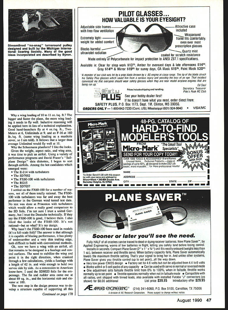
A streamlined turnaround
From Ron Peters: Michigan International Soaring Society (MISS) members built a turnaround pulley that eliminates many problems of the standard stake-type turnaround.
Their design removes protrusions (hub and U-bolt ends), shaping the unit so it’s almost impossible for the line to hang up. The base is staked to the ground and the turnaround shell slides onto it — no more hammering and loose nuts. The shell and base are made from 1/8-in. sheet steel (cut on a bandsaw and welded). The stake is an 18-in. length of 1-1/2-in. angle iron with a plate welded on top; the angle slips through the base plate to hold it to the ground.
They tested it for a season with fantastic results and no hang-ups. Designer: Fred Stafford, Wayne, MI. This has cut down on long walks to the other end of the field.
New products department
- Trim-sheet material from Eagle Products, P.O. Box 4609, Covina, CA 91723; tel. 1-818-393-1311. Material measures about .007 in. thick, has extremely strong adhesive, available in two-, three-, or three-color combinations. Mask sections and pull the face to the area. Should be available at hobby stores.
- Model Saver from Aero-Electric, P.O. Box 283, Goleta, CA 93116; tel. 1-805-687-4206. A 4 x 12-in. transparent sheet, .013 in. thick, very tough with tenacious adhesive, conforms to compound curves — use to protect nose and wing tips. Sells for $1.95 per sheet (direct, including postage) or from hobby shops.
Cross-Country clarification
In February I called Chicago’s SOAR club’s Great Race “the granddaddy of Cross-Country races” because it’s the oldest X-C race still conducted, having started in 1976. Jerry Kranock and Dave Peltz pointed out the first X-C race was organized by Jerry’s San Fernando Valley Silent Flyers (SFVSF) in fall 1975. SFVSF ran the contest until about 1987. Jerry set FAI-recognized distance records in 1972 and 1974; Jerry and Dave co-authored the FAI F3H X-C rules. This corrects the record.
Max Splat / Gall (continued)
Engines generally unload 10–20% in the air, so ground rpm may be below the rpm needed for peak power even though the system works well once airborne.
If you want the highest possible power (e.g., FAI racing), you must make Maximum Splat occur in the engine’s power band and in the air. Maximum Splat depends on pipe length and engine rpm. If you know the engine’s peak rpm (often listed by manufacturers), make a bench prop that will spin near that speed to set the pipe or header. This is better than gradually cutting the pipe until it rings at the desired rpm. Always balance the prop and wear eye protection.
As you approach target rpm on the bench, the pipe may assist and the rpm can be a little high. Also, the last cut will often go a bit too far. Start with a bench prop that’s a little large (e.g., 2,000 rpm below target) and set a target rpm a bit below the engine’s actual peak (e.g., 1,000 rpm lower). If you overshoot the target, use a slightly larger bench prop. Shorten the pipe by about 1/4 in at a time until rpm no longer increases with each cut.
When done, whittle a prop that turns at about 80–90% of the engine’s peak rpm to account for approximately 15% unloading in the air. Fly the plane and use trial and error to find the exact ground rpm in flight.
Muffled tuned pipes aren’t a cure-all, but they elegantly resolve the twin problems of insufficient muffling where power is needed and insufficient power where muffling is needed. If more modelers used these devices, we might end the noise bickering and get on with enjoying the hobby. May the Splat be with you!
Transcribed from original scans by AI. Minor OCR errors may remain.

