
RADIO CONTROL SOARING
Byron Blakeslee 3134 N. Winnebago Dr., Sedalia, CO 80135
MORE ON THE FALCON 880/SD7037
Ernie Barter, head of VMC Flight (manufacturer of the Model 20 retriever), sent a letter and photos of his new Falcon 880. In my February column I wrote about flying Mark Allen's 880 with the SD7037 airfoil. That ship weighed 59 ounces and flew great, but I mentioned it seemed a little too light and that there was no provision for adding ballast. Ernie writes:
"Enjoyed the article re: Falcon 880/SD7037. I am just now getting used to my 880 at 59 ounces, and you're correct, it is too light. I have the 7037 airfoil pre-sheeted from Flite Lite, and at 59 ounces, it floats. I have ballasted to 64, then 69 ounces, and at both weights it is a different airplane. I have more testing to do, but I think the 64-ounce weight is about right, although there is no noticeable difference between 64 and 69.
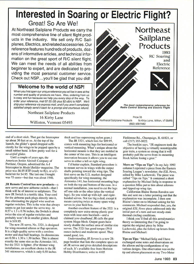
"For the 'for-what-it's-worth' department, I built the Falcon without a rudder, and the stab servo is in the tail. Rudder spar/sub-spar are fin stiffeners, and when taped in place, the fin gets very rigid. This configuration required two ounces of nose ballast. I can't imagine building a sixth-servo rudder linkage and staying within 59 ounces.
"Handling is superb without a rudder. Turns to aileron differential. Thermal turns are just fine, and slow-speed approach turns with flaps/crow are not a problem."
Thanks to Ernie for sharing his findings. I've seen electrics with the elevator servo in the fin, but this is the first time I've heard it done with a glider. Electrics naturally have built-in nose weight (motor and battery), so a tail elevator servo can aid balance. With the elevator servo in the fin and directly coupled to the stab, linkage slop should be reduced.
Gliders usually need added nose weight, so the usual procedure is to put heavy components (battery, servos) as far forward as possible. Ernie's approach eliminates a rudder servo and saves weight while keeping handling excellent.
JR Remote Control: new servo and airborne switch
JR Remote Control introduced two new items that sailplaners may like:
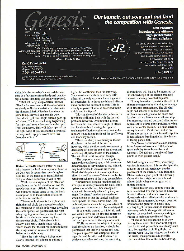
- JR Switch: The cord for the airborne battery pack plugs directly into this switch, eliminating the usual pigtail wire that often gets lost under the servo tray. Size: 0.57 x 1.30 x 0.076 inches. It's about twice the size of regular switches and may not fit in smaller gliders. Retail list: $19.95.
- JR servo No. 3321: Designed for wing-mounted aileron or flap operation. Features a coreless motor, dual ball bearings, and a new extra-strong plastic gear train (JR calls it Mega-Mesh) with near-zero backlash and a claimed zero deadband. Dimensions: 0.58 x 1.30 x 1.30 inches; torque: 59.8 oz-in; moderate speed. The 3321 is lighter than the Airtronics 141 and comes with mounting lugs for horizontal or vertical mounting; the horizontal mounts are molded in the center of the case so one servo can be used in either left or right wings. Retail list: $89.95.
For thinner wings, the JR 341 microservo is only 0.50 inches thick and has strong nylon gears.
Understanding JR Servos is a new 28-page booklet listing specs for all JR servos; it's available free from Horizon Hobby Distributors. Write to 4105 Fieldstone Rd., Champaign, IL 61821, or call (217) 355-0022.
Hand-launched Gliders (HLG) and the Zip Start
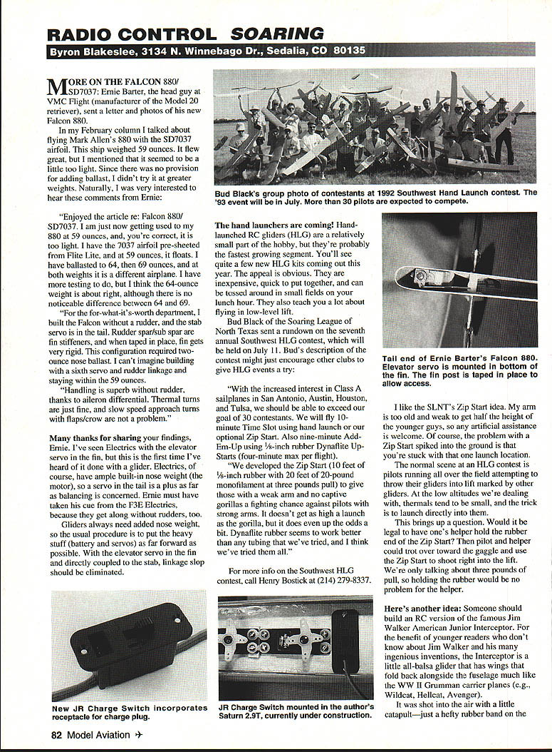
Hand-launched RC gliders (HLG) are a relatively small but fast-growing segment. They are inexpensive, quick to assemble, suitable for small fields, and teach flying in low-level lift. Bud Black of the Soaring League of North Texas sent details on the seventh annual Southwest HLG contest (to be held July 11). The event may exceed its goal of 30 contestants and will include:
- 10-minute Time Slot using hand launch or optional Zip Start.
- 9-minute Add-Em-Up using 1/8-inch rubber Dynaflite Up Starts (four-minute max per flight).
Zip Start (developed to help pilots with weaker arms) specs: 10 feet of 1/8-inch rubber with 20 feet of 20-pound monofilament, about three pounds pull. It doesn't reach the height of the strongest throwers but evens the odds. Dynaflite rubber works better than tubing in their tests.
For more info on the Southwest HLG contest, call Henry Bostick at (214) 279-8337.
I like the Zip Start idea — for those of us with weak arms it's helpful. One drawback: if the Zip Start is spiked in the ground, you're stuck at that launch location, while HLG contests often require running across the field to throw into small, localized thermals. A possible tweak: have a helper hold the rubber end so the pilot and helper can move together toward lift; three pounds of pull is easy for a helper to hold.
Jim Walker American Junior Interceptor — RC idea
Here's an idea: someone should build an RC version of Jim Walker's American Junior Interceptor. For younger readers unfamiliar with Jim Walker: the Interceptor was a small, all-balsa glider whose wings folded back alongside the fuselage (like WWII Grumman carrier planes). It was launched with a small catapult — essentially a hefty rubber band on the end of a short stick — and got up about 30 feet. At the top of the launch, speed dropped enough for a small rubber band to pop the wings open. It flew surprisingly well for a no-airfoil glider. The American Junior Aircraft Company of Portland, Oregon, advertised the A-J Interceptor in Model Builder years ago; it was inexpensive and simple.
"Tips on Tips" — ailerons and tip stall (reprint and commentary)
In July 1992 I reprinted a piece from the Eastern Soaring League's newsletter (ESL News), edited by Mike Lachowski, called "Tips on Tips." The piece included a short explanation by Michael Selig about ailerons and tipped-up wing tips. Blaine Beron-Radwoon sent a letter pointing out the explanation was incomplete; Michael Selig responded that the original piece addressed only the initial part of a turn and not steady-state thermal circling. Below are the original item and the follow-up letters.
Tips on Tips (original, Mike Lachowski): "Michael Selig and I have exchanged some notes and observations on the aileron and tip configurations of my various designs. One observation was on the tip and aileron placement on my Two-Meter ships. Number two ship's wing had the ailerons a few inches from the tip and bent the tips upward. Handling was greatly improved."
Michael Selig's brief explanation in the original: "Thanks for your note with the observation on the tip stall characteristics in relation to the ailerons. Mark Allen has found out the same thing. Maybe I can explain why. Consider a right turn. Right aileron goes up, left down. The low-speed wing (right wing for a right turn) sees a downwash at the tiplet from the aileron. This will delay tip stall on the right wing. If you extend the ailerons all the way to the tip, you won't have this favorable effect."
Blaine Beron-Radwoon's letter: "I read with interest the lead item in your column in the July MA. It seems that something has been lost in the translation from Michael Selig to Mike Lachowski to you!
"While the description of the effect of the ailerons on the lift distribution (coefficient of lift—Cl distribution) on the wing tip area makes sense to me, the basic assumption as to the direction of aileron deflection is mistaken.
"The example shown is for a plane in a right thermal circle (as opposed to a right roll maneuver in which both wings are going the same speed). As pointed out, the right wing is going more slowly since it is on the inside of the circle and covering less distance per circle. If the plane is in a steady-state bank, then it is not rolling, which means that the net roll moment due to the wings must be zero—the left wing balances the right wing.
"Since the right wing is flying more slowly than the left, it must be pulling a higher lift coefficient than the left. Since most aileron ships have very little dihedral, the only way to achieve a greater lift coefficient is to droop the inboard aileron and/or reflex the outboard aileron. This is exactly opposite of what is described in the article and the figure!
"Moving the end of the aileron inboard a few inches still may help with the tip stall problem, however. Dropping the aileron increases the local effective angle of attack and local camber. Leaving the tip area unchanged effectively gives washout at the inboard tip, reducing the local lift coefficient and tending to stall.
"There is a sharp discontinuity in the lift distribution at the end of the aileron which the flow tends to even out by decreasing lift near the end of the aileron and increasing lift just outboard of the aileron. The net effect is still washout, though.
"The purpose or value of bending the tip panel (without aileron) up to a fairly extreme dihedral angle is unclear to me. While it may be desirable to increase the overall dihedral of the plane to increase spiral stability, it would be more efficient to do this by bending much more of the wing up much less.
"Furthermore, bending just the small tip area up a lot is likely to cause tip stalls. If the tip has a lot of dihedral, then its angle of attack will be strongly affected by the yawing. The aircraft tends to yaw outboard when circling so that the vertical stabilizer lines up with the local, curved flow. This outboard yaw increases the angle of attack of the tip panel, increasing the chance of tip stall.
"If you really wanted to inhibit tip stall, you would leave the tip dihedral at zero or perhaps even bend it down a bit so that outboard yaw reduced the angle of attack.
"While we are on the subject of cutting back the aileron tip location, it should be pointed out that this will reduce roll rate. The plain tip areas will damp roll motion regardless of aileron deflection. To achieve equivalent roll rate, the remaining aileron throw will have to be increased, or the inboard edge of the aileron extended inboard, reducing potential flap area."
Blaine also noted the analogy between aileron arrangement and dihedral arrangements: outboard ailerons are like a three-panel polyhedral wing; full-span ailerons are like V-dihedral; cutting ailerons back from the tip is equivalent to flattening the last few inches of the tip panels. He referenced his Model Aviation articles on dihedral (Aug–Nov 1988) and spiral stability (Sept–Oct 1990) for more detail.
Michael Selig's response: "Yes, something was lost in translation. It is not the tiplet that reduces the tip stall tendency, but the placement of the aileron. Aside from this, Blaine makes a good point. The drawing shows the aileron further in. The inboard aileron (right wing aileron in the example) goes up to initiate the turn.
"This situation only applies when the turn is initiated. For this period of time, the inboard aileron produces a favorable downwash, which alleviates the tendency to tip stall. This argument, however, does not hold once the glider is in steady-state circling flight. In this situation it becomes necessary to hold the opposite aileron to prevent the over‑bank tendency and maintain coordinated flight.
"There is one explanation as to why having the ailerons stop short of the tips is best for tip stall prevention in a steady-state turn. For a glider in circling flight, the inboard wing (i.e., the wing on the inside of the circle) must produce a higher lift coefficient than that of the outboard wing. If the glider is made to stall, the inboard wing will stall first since it must operate at a higher lift coefficient. Specifically, the stall will first take place over the inboard aileron since this is doing the most work to generate lift. If the aileron is extended to the tip, tip stall will occur when the aileron stalls. If the stalled portion of the wing is moved toward the fuselage, the stall is no longer characterized as a tip stall. This can be achieved by moving the ailerons toward the fuselage since this is the part of the wing that stalls first."
Thanks to Blaine and Michael — their exchange clarifies the difference between turn initiation and steady-state circling and why ailerons that stop short of the tip can help reduce tip-stall tendency. Michael also reports he is now married and is an assistant professor of aeronautical and astronautical engineering at the University of Illinois, Urbana–Champaign, and continues to work in the model glider field.
Blaine Beron-Radwoon is remembered by many as the designer of the Mirage 112-inch-span glider from the mid-1970s, and for his work with Paul MacCready's Gossamer Albatross and the Solar Challenger. He is now a configuration designer for McDonnell Douglas in Long Beach, California.
Airfoil notes and Soartech
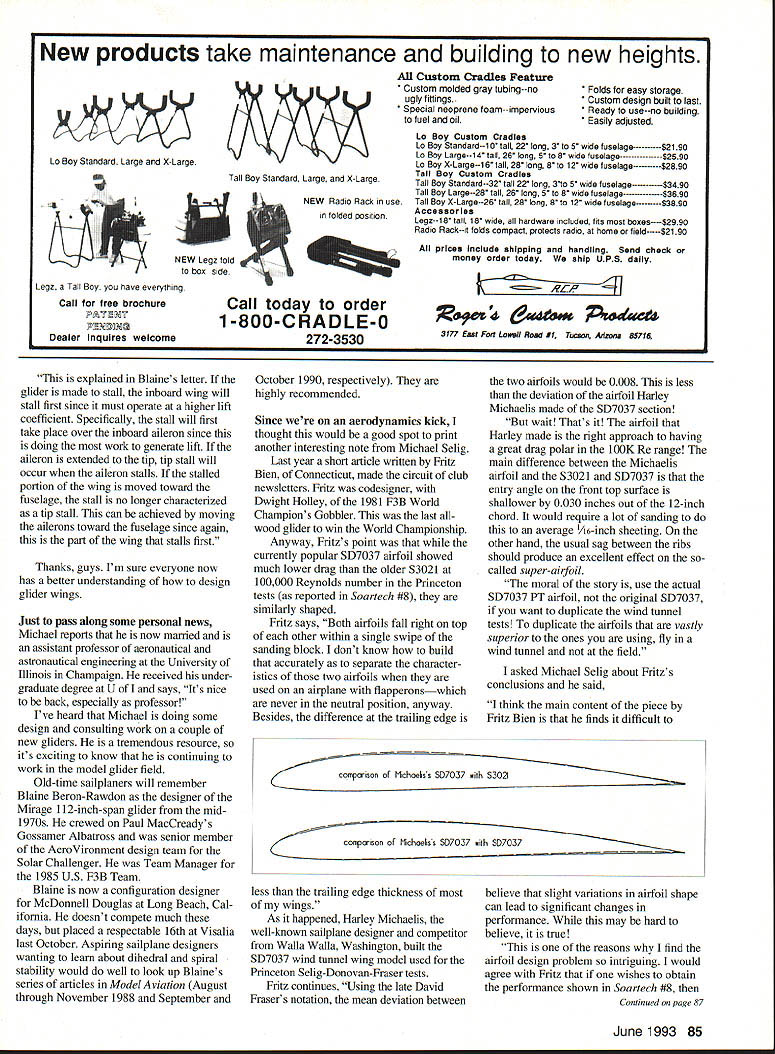
Fritz Bien (Connecticut), co-designer of the 1981 F3B World Champion's Gobbler, observed that the SD7037 airfoil and the older S3021 are very similarly shaped — in practice they can fall within a single pass of the sanding block. Harley Michaelis built the SD7037 wind-tunnel model used in the Princeton Selig-Donovan-Fraser tests; Fritz notes that the main difference between the Michaelis airfoil and the S3021/SD7037 is a shallower entry angle on the front top surface (about 0.030 inches out of the 12-inch chord). Small construction variations can matter at 100k Reynolds numbers. Fritz's moral: to get the wind-tunnel results you may need to use the precise PT test model coordinates; otherwise small deviations can change performance.
Soartech publications:
- Soartech #9 is available for $8 (U.S., postage paid). Contents include:
- "The Use of Wind Tunnel Data in the Design of RC Contest Model Sailplanes" — Martin Simons
- "Static Longitudinal Stability with the CROCCO Method" — Ferdi Gale
- "Fear the Flying Wing" — Noel Falconer
- "On Wing Load Computation" — Max Chernoff
- "What Can Be Learned from Paper Airplanes" — Hewitt Phillips
- "Built-In Sheeting" — Dennis Oglesby
- Soartech #10 is being planned and will be over 200 pages with a Martin Bamert photo essay on composite model creation.
- Soartech #8 ("Airfoils at Low Speeds") is still available; price and availability details can be obtained from Henk Stokely. Send an SASE to Soartech Journal, 1504 N. Horseshoe Circle, Virginia Beach, VA 23451.
Additional Soartech items:
- Airfoils at Low Speed data disk (ASCII text files from the Princeton tests) — $12 (U.S./Canada) on 360K IBM disk.
- Sailplane Design Performance Analysis Program (version 3.4) — includes wind-tunnel airfoil data and sample aircraft parameter files; manual included — $35 (U.S./Canada) on 360K IBM disk. Order from Soartech Journal at the address above.
RADIO CONTROL: SOARING (additional notes and miscellany)
Gee Bees turn you on? Write to Henry Haffke, RR #1, Box 22, Londonderry, VT 05148. The documentation information is out there — you just have to tap the right source for giant-scale perfection.
Ron Weiss has a 1/3-scale Fokker D.VII "Flying Razor" with a 9 ft 3 in wingspan (1,650 sq in area), 74-inch fuselage, and weighing 30 lb. It uses a Kioritz 2.4 cu in engine. Ron found authentic three-views in World War I Aeroplanes and in Heinz J. Nowarra's work for Harleyford Publications. The model has flown since 1985 and closely duplicates the original's flight characteristics. Ron offers his drawings — contact him at 20 Linda Pl., Huntington, NY 11743 (include a large SASE). He also offers 1/3-scale plans for the 1930 Fleet 2 biplane.
Columnists get gray hair from product news releases — most are helpful, some are obtuse. Keep 'em big, fly 'em big. Back with you next month!
Transcribed from original scans by AI. Minor OCR errors may remain.

