
RADIO CONTROL: SOARING
Daryl Perkins 4234 Petaluma Blvd., North Petaluma, CA 94952
I'm a born-and-raised southern California boy, and the nice thing about southern California is that it never gets really cold. Cold to me was when you had to put on long pants to go flying, or when those killer, hat-sucking, small-child-collecting thermals would take you up only about 1,000 feet. The toughest decision that southern California fliers have to make is when to break for espresso, and I have actually been on the field when a Domino's Pizza guy has shown up. Modeling life is good in southern California!
I finally understand why the rest of you need building projects to keep busy during the off-season: last summer I began working in northern California for Mark Allen of Allen Development (Mark is the former owner of Rite‑Lite Composites). They never told me how cold it gets up here. I've never been in a situation where I couldn't fly year‑round wearing only T‑shirts and shorts. Not only does it get cold up here, but it actually rains. (Water, falling from the sky—what a concept!)
So I have decided to build a project model—the new world‑beater, if you will. I will take you step‑by‑step through the design process: airfoil and planform choices, construction techniques, radio installation and servo choices, and all the way through first flight and first speed run. We will utilize the ultimate in building techniques and the newest in composite materials. I know that a lot of you are saying, "Great, we are going to learn about an F3B model!" While this is true, the model will be designed to be as efficient a machine as can be built using today's homebuilding technology.
The planform and size of the model should be very close to the optimum contest duration model. The only real alteration you would make would be to change airfoils to suit your personal preference.
An important aspect of any model is the name, and I asked my girlfriend what she thought. A model should be a part of the designer and should be named as such; it should reflect the attitude, the flying style, or the ego of the designer.
"Your ego?" she said, "how about 'huge,' 'massive,' or maybe, 'astronomical'?"
Seeing that she wasn't going to be any help at all, I referred to one of the classic movies of all time, Top Gun, and decided to settle on Maverick. Look for Project Maverick in future columns.
Big News: Airfoil Wind‑Tunnel Tests
Without a doubt, the biggest impact on RC soaring today was made by Michael Selig, John Donovan, and the late David Fraser with their famous wind‑tunnel testing program at Princeton University. The results of those tests, published in Soartech 8 (1989), profoundly affected the shape and direction of current sailplane designs and greatly enhanced our sport.
A new testing program has been proposed and will be implemented at the University of Illinois at Urbana‑Champaign (UIUC). The organizers are seeking support and assistance from experienced modelers. The full letter follows.
Letter from the UIUC Program
Dear Modeler:
We are searching for a group of experienced modelers to build a variety of airfoil wind‑tunnel models for tests at the University of Illinois at Urbana‑Champaign (UIUC). A low‑speed, low‑turbulence wind tunnel has been instrumented to take lift and drag measurements on airfoils at low speeds over the Reynolds number range from 60,000 to 300,000. The scope of the airfoil wind‑tunnel tests will be limited only by the number of wind‑tunnel models provided and the amount of funding received.
Hopefully, the proposed modeler‑supported airfoil test program will become self‑sustaining. Your support and help of any kind will be acknowledged in reports on the project to be published by Herk Stokely in Soartech. We plan to publish the results through Soartech frequently—possibly twice per year.
A similar undertaking (with substantial support from modelers) was started by Michael Selig, John Donovan, and the late David Fraser in 1987 at Princeton University. In a two‑year period, over sixty various low‑speed airfoils were wind‑tunnel tested, involving over 1,200 hours of wind‑tunnel test time. The results were published in Soartech 8 in 1989, and many of the new airfoil designs produced and tested during the program are now widely used on RC sailplanes. As of November 1993, over 2,200 copies of Soartech 8 are in circulation worldwide. (Soartech 8 is available from Soartech Journal, c/o Herk Stokely, 1504 N. Horseshoe Circle, Virginia Beach, VA 23451.)
At present, there is a need for new airfoils for RC sailplanes. For example, RC hand‑launch soaring is booming, but few good airfoils (e.g., E387 and SD7037) exist for such sailplanes. Sailplanes for the new F3J competition are just beginning to evolve, and new airfoils will probably be required. What will the new airfoils look like? In the past, only a few airfoils (e.g., HQ 15/85, RG15, SD7003) have been favored for F3B competition.
In shape, handling, and performance, the SD7003 is quite different from the other airfoils mentioned. These significant differences suggest that it may be possible to design new airfoils that have better overall characteristics for F3B competition.
In addition to the design and wind‑tunnel testing of new airfoils, several existing airfoils should be tested. The SD7037 and RG15 are quite popular and are often used with flaps. The flap effectiveness of these airfoils should be quantified through wind‑tunnel tests, and the results should be used in the design of new airfoils.
There is also a need for new airfoils for RC sport, aerobatic, and electric models, as well as RC helicopters. Often, old NACA airfoils are used for these aircraft. Compared with airfoils that could be designed today, these NACA airfoils (which were designed decades ago, mostly by trial and error) are inferior.
At the time the NACA airfoils were designed, little was known about the complex aerodynamics of airfoils operating at low Reynolds numbers (airfoils with small chords at low speeds, such as those on model aircraft). In recent years, much has been learned about low Reynolds number aerodynamics, and this knowledge has successfully been applied to the design of new airfoils for R/C sailplanes, ushering in a new era in R/C soaring.
Overall, R/C sailplane performance has improved dramatically. Older airfoils are no longer used. R/C power aircraft performance could likewise be dramatically improved through the use of newly designed, specially tailored airfoils.
Unique airfoil design requirements also exist for other categories of model aircraft. For example, FAI free flight aircraft (which incorporate both a powered launch segment and gliding flight) operate over a wide range of speeds. In the past, many airfoils with good performance characteristics have been designed for FAI free flight. These airfoils should be wind‑tunnel tested to quantify their performance. The results gleaned from the tests could then be applied in the design process in an effort to develop new airfoils with improved performance.
Also, the Society of Automotive Engineers (SAE) sponsors an annual model airplane design competition in which university student teams design, build, and fly an R/C cargo aircraft. The record cargo weight that has been carried now stands at 23‑1/4 pounds for a model with a .60‑sized engine and 1,200 square inches total projected area. Conceivably, this record could be broken by an aircraft with an airfoil (or airfoils) specifically designed for the competition.
Clearly, the need for new airfoils and data on existing airfoils is not limited just to R/C sailplanes, but applies to any type of model aircraft where better handling quality and overall performance are desired.
Other topics of interest include the effects of turbulators, contour accuracy and airfoil blending. Are trips simply repairs to otherwise bad airfoils, or can trips be integrated with the airfoil and result in improvements over, say, the SD7037? The Princeton tests began to address this issue, but many questions still remain. For example:
- What is the best trip height for a given airfoil?
- What is the best trip geometry?
- Where should the trip be located for best performance?
- What type of airfoils respond best to trips?
The Princeton tests also shed some light on how accurate airfoils must be in order to achieve expected performance, but a more systematic effort should be made to test the best airfoils for sensitivity to contour accuracy.
It is also unlikely that the best performance can be obtained from a single airfoil used along the entire wing span. Rather, airfoils should be blended from root to tip. This is especially true for flying wings. Companion airfoils for blending should be designed for use with the most popular existing airfoils, e.g., SD7037 and RG15.
If you believe that we have overlooked an important area, we would be interested in your input and may consider expanding the scope of the project. The number of airfoil models to be tested has not been predetermined; rather, it will depend on the level of interest and support from the modeling community.
The wind tunnel models should be 33% in span with a 12‑inch chord and can either be built‑up or foam core. To ensure a uniform contour, the built‑up models need to be fully sheeted. For foam core models, we may be able to supply two 12‑inch chord wing templates.
The surface finish can either be fiberglass or MonoKote; however, we are interested in the effects of surface finish and will consider testing models with non‑smooth surfaces. The models will be attached to the wind tunnel balance by standard model wing rods.
Standard model construction techniques should provide the necessary strength (supporting 15–20 pounds of lift when pinned at both ends). The brass tubing and collars for the models will be supplied along with full‑scale plots and/or coordinates of the airfoil, if requested.
The airfoils will be tested in the UIUC open‑circuit 3 x 4 foot subsonic wind tunnel. The turbulence intensity level is minimal and more than sufficient to ensure good flow integrity at low Reynolds numbers. The experimental apparatus used at Princeton will be modified for the UIUC tests.
Lift and drag measurements for each airfoil will be taken at Reynolds numbers of:
- 60,000
- 100,000
- 200,000
- 300,000
In some instances, it may be possible to take limited data over an expanded range (20,000–1,000,000).
The lift characteristics will be determined through force‑balance measurements, while the drag will be evaluated by the momentum method through the use of a wake‑rake traversed through the wake at four spanwise locations. We are also interested in airfoil pitching moment measurements, but the current apparatus does not have such a capability.
How to get involved / Contact
If you are interested in building wind tunnel models for the tests, please write, call, fax, or send e‑mail. Correspondence and calls for information should be directed to the graduate student in charge of the project:
James J. Guglielmo, Coordinator Dept. of Aeronautical and Astronautical Engineering University of Illinois at Urbana‑Champaign 306 Talbot Laboratory, 104 S. Wright St. Urbana, IL 61801‑2935 Fax: (217) 244‑0720 E‑mail: jjgug@uxh.cso.uiuc.edu
Funding & Donations
The program will be self‑sustaining so long as funds are made available for equipment maintenance/upgrades and graduate student stipend support and tuition and fees (approximately $16,000 per year, per student).
The initial goal is to raise enough money to support at least two graduate students for a three‑year period. It is envisioned that a small level of support from a large number of modelers and modeling enthusiasts could sustain the airfoil design and wind tunnel test program indefinitely. The impact on model aviation could be tremendous.
Contributions can be mailed to:
Prof. Michael Selig Dept. of Aeronautical and Astronautical Engineering University of Illinois at Urbana‑Champaign 306 Talbot Laboratory, 104 S. Wright St. Urbana, IL 61801‑2935
Please make checks payable to: University of Illinois, AAE Dept. Also, please write on the check: "Selig—Wind Tunnel Testing/AAE Unrestricted Funds" and provide a letter stating that your contribution is to be used by Professor Selig and his group of students (both undergraduate and graduate) in support of the airfoil wind tunnel tests. Feel free to circulate this letter to others who might have an interest in our plans.
I don't know how I could have circulated this information to a larger group. From being on the past two US Soaring teams, I know how generous the modeling community can be. Let's all dig deep to help fund this effort. We'll all be the beneficiaries.
Another New Design
One of the nice things about working within the soaring community is being privy to all the new, trick information.
Mark Allen, the designer of the Falcon 880 and a subsequent series of sailplanes, is coming out with a new model called the Skyhawk. If I know Mark, it should be a winner. The Skyhawk will span approximately 106 inches and will transition from an S‑3021 at the root to a modified S‑3021 at the tip. Hold on to your hats, folks—this new contest model will not be obeche sheeting over foam, as with the traditional contest models of today, but will be of built‑up construction. This is good news for those of you who still retain those building boards and T‑pins.
The kit will have a fiberglass fuselage with a standard tail configuration and has been designed around standard‑sized radio equipment. The wing will consist of laser‑cut ribs and carbon spars to withstand the punishment some of us can put a model through.
Mark says it should be an ideal first aileron‑flap, high‑performance model. I have seen the preliminary drawings and the fuselage plug, and Mark's new effort is absolutely gorgeous! At a projected all‑up weight of 50 to 55 ounces, this model should be a spot‑lander extraordinaire. If you want one, call Ed at Slegers International: (201) 366‑0880.
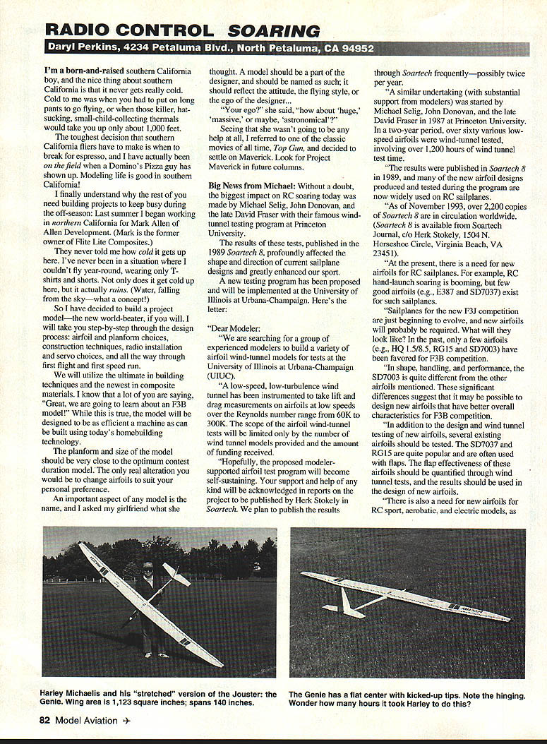
The Genie (Harley Michaelis)
Here's what Harley Michaelis has to say about his beautiful new model, the Genie:
- Builders into vacuum‑bagging may be interested in knowing I've done a stretched version of the Jouster with a composite wing that I call the Genie.
- The span is 140 inches and the wing area is 1,123 square inches.
- The fuselage profile is the same as the Jouster, but 6 inches longer behind the trailing edge.
- The last one weighed 74 ounces—under a 9.5‑ounce wing loading.
- The flat center section is six inches long and tapers from 10.0 inches to 8.75 inches.
- The very light tips are a bit under three feet and are triple tapered.
- Turns are sharp with ailerons and mixed‑in rudder, so only five servos are needed.
- A Kevlar/glass layup goes directly over the core. No carbon fiber is used.
- A 1/8 in. x 3/8 in. spruce spar is on top.
- The wing easily handles zoom launches and other flight stresses.
- The internal flap and DAO (direct aileron driver) mechanism are preinstalled before bagging and end up sealed in so the wing is totally clean.
- The servo wells are preformed with 1/8 balsa, avoiding the unfinished wells common in bagged wings.
- The waxed mylar is painted before bagging for a beautiful finish free of pinholes.
Harley says he has supplemental text, sketches, and a materials list to build the Genie using Jouster plans (MAY #739). He can provide text, sketches, molded canopy and blade set for $10 postpaid. For details, contact Harley (details as provided in the original notice).
Until next time: thermals.
Transcribed from original scans by AI. Minor OCR errors may remain.

