

RADIO CONTROL SOARING
Mike Garton 2733 NE 95th Ave., Ankeny IA 50021 E-mail: mike@iastate.edu
Mark Drela, professor of aeronautics and astronautics at MIT, provided two topics related to airfoils for this month: a list of airfoils he has designed for Radio Control (RC) aircraft with brief descriptions of their intended application, and a discussion of tail deadband and how it can be avoided. Mark is a leading researcher in airfoil design and has recently developed many airfoils for RC gliders, especially small or light ones that operate at exceptionally low Reynolds numbers.
Nomenclature notes:
- Many AG-series airfoils have variants for different wing sections. They are listed as "root -> tip" or "root -> mid1 -> mid2 -> tip" to suggest how to blend the family of airfoils.
- The target application and a non-exhaustive list of US glider designs using the airfoils are listed after each entry.
- The letter "a, b, c, d, or e" near the end of an airfoil name indicates the flap hinge line location at 60%, 65%, 70%, 75%, or 80% chord, respectively.
- A "t" at the end means the airfoil was thickened near the flaperon hinge line for structural reasons.
Airfoil families and intended applications:
- AG03 -> AG11: Built-up and solid-balsa small Hand-Launched Gliders (HLGs); Wood Apogee. Also for built-up small electrics needing a large speed range.
- AG04 -> AG08: Composite HLGs, strongly favor launch and run; Apogee, Taboo. Also composite S8E rocket gliders.
- AG12 -> AG13 -> AG14: Composite HLGs, roughly equal emphasis on float and run; XP-3 (polyhedral version).
- AG16 -> AG17 -> AG18: Composite HLGs, emphasis on float; Photon, Watson-Sidewinder. Also for composite light 2m poly gliders; Composite Allegro.
- AG25 -> AG26 -> AG27: Composite heavier 2m poly gliders.
- AG24 -> AG25 -> AG26: Composite 3m poly gliders; Hallett, Bubble Dancer.
- AG31 -> AG32 -> AG33: Built-up small aileron gliders; Wind Dancer (Pole Cat Aeroplane Works). (Hinge at 75–80% chord.)
- AG36 -> AG37 -> AG38: Built-up 1.5m poly HLGs.
- AG35 -> AG36 -> AG37 -> AG38: Built-up light 2m and 3m poly gliders; Allegro-Lite, Bubble Dancer.
- AG34 -> AG35 -> AG36: Built-up heavier 3m poly gliders.
- AG45c -> AG46c -> AG47c: Composite 1.5m aileron HLGs; SuperGee.
- AG45ct -> AG46ct -> AG47ct: Composite 1.5m aileron HLGs; SuperGee II, XP-3, TabooXL.
- AG44ct -> AG45ct -> AG46ct -> AG47ct: Composite light 2m aileron gliders; Aegea 2m.
- AG40d -> AG41d -> AG42d -> AG43d: Composite 3m aileron gliders; Aegea 3m.
Tail airfoils:
- HT08: All-moving small-glider tails; Allegro-Lite. (Can be thickened to 6–7% for larger gliders.)
- HT12: Discus-launch glider and light 2m tails; Allegro-Lite. (Hinge at 35–50% chord.)
- HT13 -> HT12: Heavy 2m tails.
- HT14 -> HT12: 3m tails; new Mantis.
- HT21: Built-up tails; Bubble Dancer.
- HT22: Cambered tails; SuperGee.
- HT23: Cambered discus-launch glider vertical tails; SuperGee.
Design Rationale from Mark Drela
The most popular modern RC glider airfoils (such as the SD7037, RG15, MH32, etc.) were designed for reduced Reynolds numbers in the 100,000–200,000 range, corresponding to relatively large and heavy gliders, where they perform well. However, University of Illinois (UIUC) data and numerical simulations show that their performance rapidly degrades below Re = 100,000, producing penalties on HLGs, 2m gliders, and wingtips of light 3m gliders.
A common fix has been to thin and decamber these airfoils to improve low-Re performance. This approach helps to some extent but is haphazard and generally unreliable because thinning has unpredictable effects on surface-pressure distributions; additional reshaping is almost always necessary for best behavior.
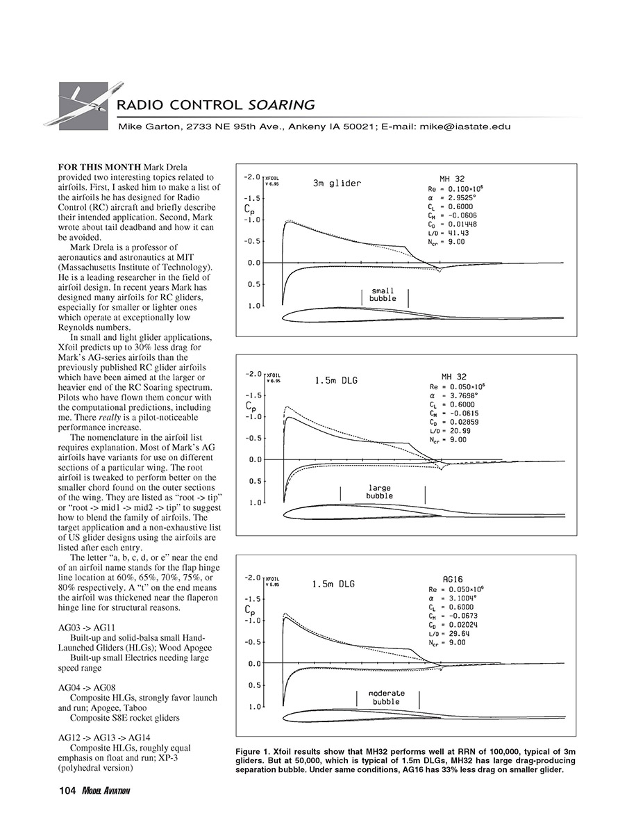
The AGxx airfoils were designed from the outset for unit-CL Reynolds numbers well below 100,000 (around Re 50,000–100,000). The upper-surface pressure distributions are carefully shaped to promote transition more aggressively than usual, shortening the laminar separation bubble and reducing the drag penalty. The lower-surface pressure distribution is also controlled to avoid strong adverse pressure gradients near the trailing edge that lead to separation. The result is low drag at Re ≈ 50,000–100,000 and good pitching moment characteristics.
A side effect of this shaping is that the maximum thickness point moves forward of usual; overall thickness and camber are reduced, which lowers maximum lift. This loss can be compensated by a slightly stretched chord and/or lower weight relative to thicker sections. Penetration is still improved despite reductions in aspect ratio or wing loading. The penetration improvement from the AG airfoils has been especially noticeable in discus-launch gliders, which operate at the lowest Reynolds numbers among competition soaring classes.
The AG airfoils designed for the largest Reynolds numbers (≈80,000) resemble other popular sections; for example, the AG24 is close to the MH32, and the AG34 is close to the S301. Other thinner AG2x and AG3x sections are relatively unique and specifically well suited to lower Reynolds numbers. The entire AG1x series is also distinct compared to common sections like the MH32.
Special features:
- AG03, AG11, and all AG3x airfoils have intentionally flat bottoms behind 30% chord for ease of construction with built-up or solid-balsa wings. Theoretical performance relative to unconstrained sections is only slightly compromised; actual performance may be better due to greater built-up accuracy with flat aft bottoms.
- AG3x airfoils also have exclusively flat facets on the upper surface behind 45% chord (e.g., behind the D-tube sheeting). This allows open-bay construction with no airfoil modification from covering. The Allegro-Lite 2m and Bubble Dancer 3m poly gliders use these features.
- The AG4x series is specially adapted for camber control. In full reflex position, the bottom surface is smooth—favorable at high speeds where premature lower-surface transition is a concern—yielding exceptional penetration. In the moderate camber position, the upper surface is smooth, which delays separation from the hinge line and delays drag rise with large flap camber, improving float characteristics. This independent top- and bottom-surface optimization with camber is common on modern full-scale sailplane airfoils and gives a wide speed range on the AG4x series despite small thickness.
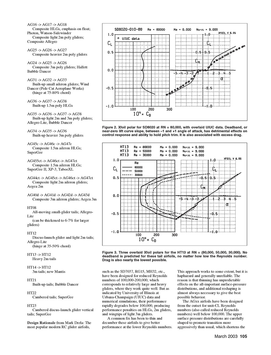
Designing airfoils specifically for low Reynolds numbers gives benefits beyond reduced drag. A common problem with tail airfoils on RC gliders is deadband (near-zero lift curve slope between about −1° and +1° angle of attack), which harms control response and pitch trim and is associated with excess drag. For example, the SD8020 tail airfoil works fine on very large gliders, but it shows deadband below Re = 100,000, where most RC glider tails operate. UIUC data and Xfoil simulations indicate the culprit is laminar separation at the trailing edge due to excessive pressure gradient and no transition/reattachment at low Re.
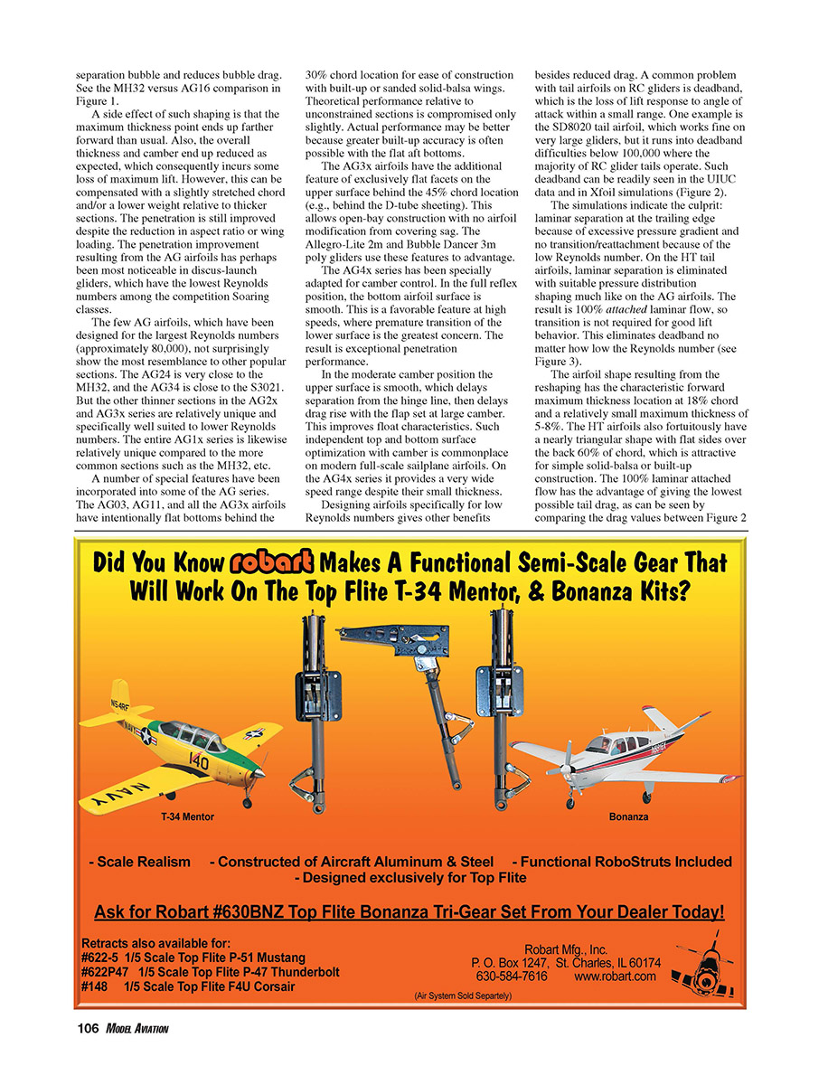
On the HT tail airfoils this laminar separation is eliminated by suitable pressure-distribution shaping similar to the AG airfoils. The result is 100% attached laminar flow so that transition is not required for good lift behavior, eliminating deadband regardless of Reynolds number.
HT airfoil characteristics:
- Forward maximum thickness location near 18% chord.
- Relatively small maximum thickness (5–8%).
- Nearly triangular shape with flat sides over the back 60% chord, attractive for simple solid-balsa or built-up construction.
- The 100% laminar attached flow gives the lowest possible total drag (see comparisons in the original figures at Re ≈ 80,000).
Sources of more information:
- Apogee, Bubble Dancer, Allegro series, many airfoils: www.charlesriverrc.org/
- SuperGee, some airfoils: www.monkeytumble.com/hlg/supergee.htm
- Allegro Lite newsgroup (much information): http://groups.yahoo.com/group/Allegro-Lite/
- XP-3, Wind Dancer (electric): www.polecataero.com/
- Taboo: http://olgol.com/taboo.html
- Xfoil: http://raphael.mit.edu/xfoil/
- UIUC: www.aae.uiuc.edu/m-selig/
Transcribed from original scans by AI. Minor OCR errors may remain.

