
RADIO CONTROL SOARING
Mike Garton, 2733 NE 95th Ave., Ankeny IA 50021; E-mail: mike@iastate.edu
This month I have a review of a new instructional mold-making DVD and a technical note submitted by Gregory Ciurpita on the pitch stability of gliders at low speed.
Bill Haymaker made the new DVD, and it features Terry Luckenbach's method of making molded parts. In particular, Terry shows how to make a Pretty Mantis glider fuselage. In the DVD, Terry mentions that he has been making molded parts for approximately 30 years; it shows. He goes into great detail about the materials, methods, and the tricks he has developed.
I have often thought about making a molded fuselage for a scratch-built glider, but experienced fabricators have consistently told me that it takes hundreds of hours to make a single hardwood plug and an epoxy-fiberglass mold.
The unique thing about Terry's method is that it takes just a fraction of the normal time to create the plug and the mold. I won't give away his secrets, but the DVD convinced me to dive into this technology for a current project. The information was enabling.
My one complaint about the DVD is that Terry did not talk about or demonstrate epoxy safety. The majority of modelers still do not understand that all people are at risk for developing epoxy allergies. Even if you have no other allergies and don't react the first 500 times you touch epoxy, eventually you will. It is cumulative exposure that eventually triggers an allergy.
I can name three glider manufacturers who have had to stop making epoxy parts within the last five years because they developed epoxy allergies. It is essential to wear gloves when you need to touch uncured epoxy. Disposable nitrile gloves cost roughly $10 for 100 at any drug store.
In spite of my one gripe, the quality of the DVD is extraordinarily high. It is 103 minutes long. I learned a great deal. It would take an individual thousands of hours to develop a similar process without the DVD. If you scratch-build, the information is priceless. I put this DVD in my must-buy category.
Bill Haymaker also sells a great DVD on Phil Barnes' methods of making composite glider wings. You can reach Bill at hayman@paonline.com or 107 Schofield Dr., East Berlin PA 17316.
What follows is technical information about glider stability by Gregory Ciurpita. Greg wrote "Low-Speed Stability" for R/C Soaring Digest (RCSD), which is the only American periodical exclusively committed to RC soaring. I obtained Greg's and RCSD's permission to include it here. I encourage glider fliers to subscribe to RCSD. It is inexpensive and has regular contributions from Dave Register, Lee Murray, Gordy Stahl, and Bill and Bunny Kuhlman, along with occasional gems of information from Mark Drela. You can find out more about RCSD at www.b2streamlines.com/RCSD.html or call (707) 578-7871.
An aircraft can be stable at higher speeds but unstable at low speeds. While a more rearward center of gravity (CG) may cause instability, it not only reduces the lift force and induced drag produced by the tail, but makes airspeed more sensitive to elevator trim setting. Adding ballast may make an aircraft more unstable, but a ballasted aircraft is normally flown faster. First, a review of an airfoil's moment coefficient (Cm). Then, an analysis of an aircraft's pitching moments over a range of CG positions.
Airfoil Moment
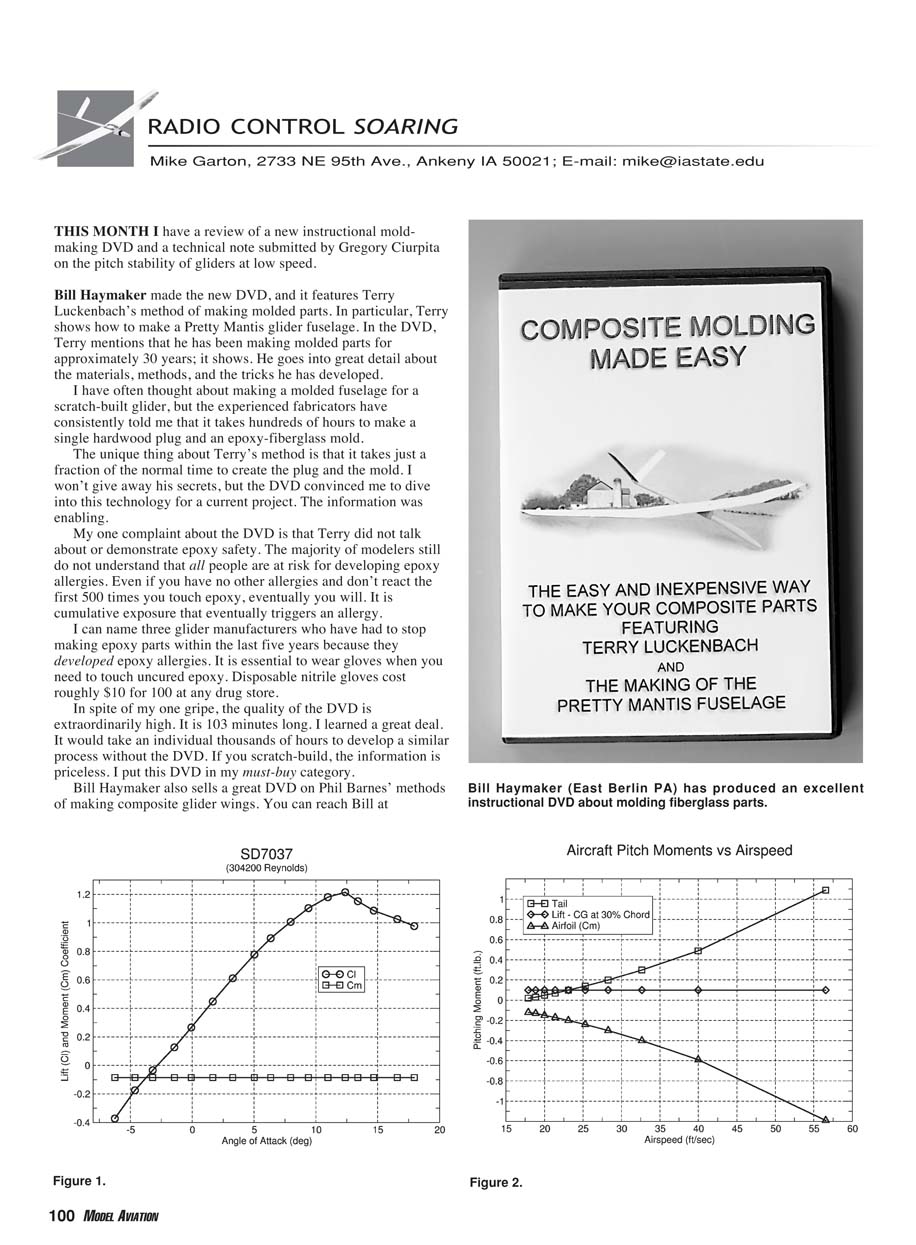
Figure 1 shows a typical airfoil measurement from the UIUC (University of Illinois at Urbana-Champaign) database. It shows curves for the lift (Cl) and moment (Cm) coefficients for various angles of attack (AOA). The lift coefficient (Cl) varies significantly, increasing steadily until stall occurs. It is common for an airfoil moment coefficient (Cm) to be approximately constant and negative.
The actual lift (L) and moment (M) are determined from the following well-known equations, where Q is the dynamic pressure, rho (0.002378 slugs/ft^3) is air density, V is airspeed (ft/sec), S is the wing area (ft^2), and C the chord length (ft):
Q = 0.5 * rho * V^2 L = Q * S * Cl M = Q * S * Cm * C
The resultant of the lift force (L) is generated through the aerodynamic center (AC) of the airfoil, typically at 25% of the chord. The moment (M) is a rotational force measured in foot-pounds or newton-meters. A wrench applies a moment on a bolt; a motor generates a moment around a shaft. A negative coefficient indicates a nose-down direction, forcing the leading edge of the wing down and the trailing edge up.
The relationship between pitching moment and the total lift of an airfoil can be confusing. As Figure 1 indicates, the Cl and Cm coefficients are independent. Consider a typical wing in a wind tunnel at a constant airspeed. As the angle of attack is increased, the lift will increase as predicted by the equations. However, the moment will remain approximately constant, even when the lift is zero. Also note that the moment does not change direction when the lift coefficient becomes negative.
Aircraft Moments
Four forces affect the overall pitch of the aircraft: the airfoil pitching moment (Cm), the lift produced by the wing, the lift force produced by the horizontal stabilizer, and drag. Lift only affects pitch when the CG is not located at the AC of the wing. Likewise, drag produces a moment when its center is either above or below the CG. The moment produced by drag will be ignored in this article.
The horizontal stabilizer and wing lift forces produce moments determined by multiplying each by their respective moment arms. Their moment arms are the distances between the aircraft CG and the AC of the tail and wing respectively. The sum of all three moments must balance (equal zero) for the aircraft to maintain its pitch. Otherwise, it will constantly rotate upward or downward.
Balanced pitch does not mean that the pitch angle will remain unchanged. For stability, there must be some mechanism to maintain the pitch orientation of the aircraft. This orientation may be affected by turbulence or a change in airspeed. A conventional approach to maintain stability is to have the horizontal stabilizer generate negative lift (a downward force). As the airspeed increases, the tail lift increases, pushing the tail down and slowing the aircraft (providing a restoring moment).
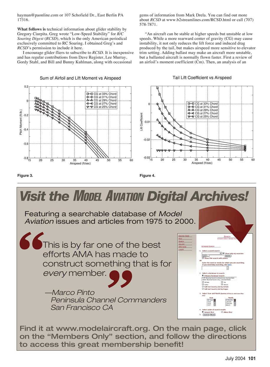
Figure 2 plots the three moment forces vs. airspeed for a CG located at 30% of the chord length (10"). The lift and its moment are constant since they must balance the weight (38 ounces) of the aircraft. The lift moment produces a nose-up force and is therefore positive.
The airfoil moment (M) is dependent on airspeed, wing area (900 sq. in.) and chord length. Cm is negative, as is its moment (M); it produces a nose-down force. As airspeed increases, it produces a greater negative moment.
The tail moment must balance (equal but opposite) the sum of the lift and airfoil moments. In this example, the horizontal stabilizer always produces a nose-up moment. Even though the horizontal stabilizer produces a negative (downward) lift force, the moment is positive (nose up) because of its moment arm.
The aircraft becomes unstable in pitch if the tail is required to produce positive (upward) lift in order to balance the sum of the airfoil and lift moments. This would be indicated by a negative (nose-down) tail moment, and is most likely to occur at low airspeeds.
Low-Speed Instability
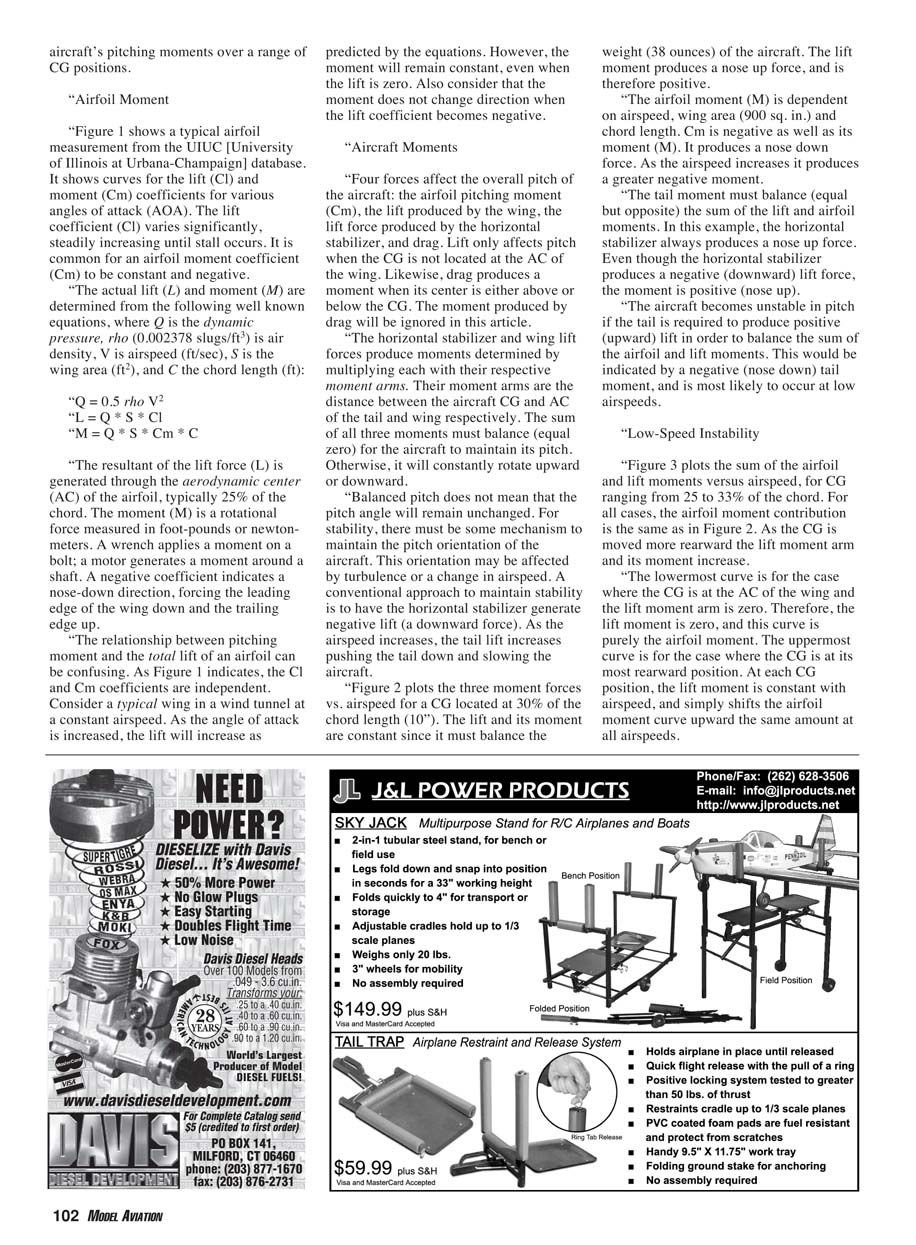
Figure 3 plots the sum of the airfoil and lift moments versus airspeed, for CG ranging from 25 to 33% of the chord. For all cases, the airfoil moment contribution is the same as in Figure 2. As the CG is moved more rearward the lift moment arm and its moment increase.
The lowermost curve is for the case where the CG is at the AC of the wing and the lift moment arm is zero. Therefore, the lift moment is zero, and this curve is purely the airfoil moment. The uppermost curve is for the case where the CG is at its most rearward position. At each CG position, the lift moment is constant with airspeed, and simply shifts the airfoil moment curve upward the same amount at all airspeeds.
As the CG is moved rearward, it is more likely to cause an unstable situation at low speeds. As the 33% case shows, a negative tail moment is required below an airspeed of 20 ft/s. A negative tail moment requires a positive (upward) tail lift, which no longer provides a pitch-correcting mechanism.
Airspeed Sensitivity
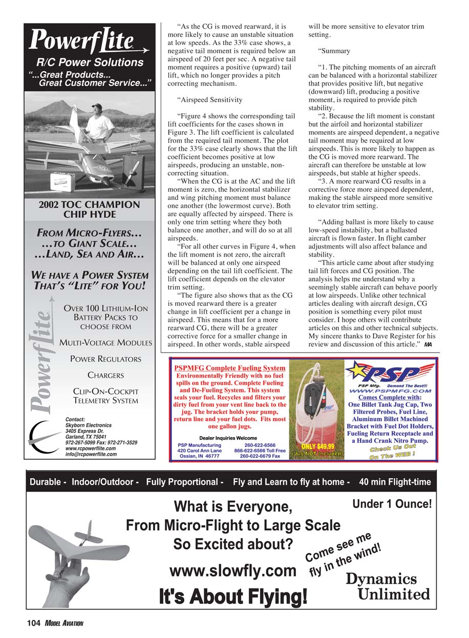
Figure 4 shows the corresponding tail lift coefficients for the cases shown in Figure 3. The lift coefficient is calculated from the required tail moment. The plot for the 33% case clearly shows that the lift coefficient becomes positive at low airspeeds, producing an unstable, non-correcting situation.
When the CG is at the AC and the lift moment is zero, the horizontal stabilizer and wing pitching moment must balance one another (the lowermost curve). Both are equally affected by airspeed. There is only one trim setting where they both balance one another, and they will do so at all airspeeds.
For all other curves in Figure 4, when the lift moment is not zero, the aircraft will be balanced at only one airspeed depending on the tail lift coefficient. The lift coefficient depends on the elevator trim setting.
The figure also shows that as the CG is moved rearward there is a greater change in tail lift coefficient per change in airspeed. This means that for a more rearward CG, there will be a greater corrective force for a smaller change in airspeed. In other words, stable airspeed will be more sensitive to elevator trim setting.
Summary
- The pitching moments of an aircraft can be balanced with a horizontal stabilizer that provides positive moment even while producing negative (downward) lift, but negative (downward) lift at the tail is required to provide pitch stability.
- Because the lift moment is constant but the airfoil and horizontal stabilizer moments are airspeed dependent, a negative tail moment may be required at low airspeeds. This is more likely to happen as the CG is moved more rearward. The aircraft can therefore be unstable at low airspeeds, but stable at higher speeds.
- A more rearward CG results in a corrective force that is more airspeed dependent, making the stable airspeed more sensitive to elevator trim setting.
Adding ballast is more likely to cause low-speed instability, but a ballasted aircraft is typically flown faster. In-flight camber adjustments will also affect balance and stability.
This article came about after studying tail lift forces and CG position. The analysis helps me understand why a seemingly stable aircraft can behave poorly at low airspeeds. Unlike other technical articles dealing with aircraft design, CG position is something every pilot must consider. I hope others will contribute articles on this and other technical subjects. My sincere thanks to Dave Register for his review and discussion of this article.
MA
Transcribed from original scans by AI. Minor OCR errors may remain.

