
RADIO CONTROL SOARING
Mike Garton, 506 N.E. 6th St., Ankeny IA 50021; E-mail: mike@iastate.edu
Editor's note
This is the latest in our series of guest-authored Soaring columns. Please let us know whom you prefer to write the column on a permanent basis.
Introduction
I started flying radio control gliders in 1981, before I was old enough to legally drive a car. If you are now trying to guess, I am younger than the average glider pilot (30). My early interest in glider aerodynamics and structures led me to seek degrees in Aerospace Engineering and Engineering Mechanics. I now work as a scientist at Iowa State University, creating technology to make full-scale aircraft safer.
I fly all phases of thermal soaring and have competed in all types of glider events. Hand-launch gliders have provided me with the most enjoyment. The best lunch breaks I have are those with no food at all.
Although I often build a kit to save time, I get more satisfaction from scratchbuilding. I am very technical by nature, but I will target most of the content of this column at the sport glider flier.
I am very accessible through E-mail (mike@iastate.edu) or phone: (515) 294-1429 days, and (515) 965-8593 evenings or weekends. I will always listen, and I do appreciate constructive criticism.
Noise, long servo leads, and glitches
Long servo leads with multiple connectors in-line are now commonplace in gliders with ailerons. This has come about because it is easier to make a slop-free linkage when the servo is very close to the control surface. The long leads increase the chance of radio glitches, because the wire can act as a receiving antenna and feed noise back into the receiver through the servo connections. The risk increases with lead length, and also increases if your leads happen to be close to an integer fraction of your wavelength.
For instance, if you fly with a radio in the 72 MHz band, your wavelength is approximately four meters. If your servo leads happen to be a nice round fraction of four meters, you are unintentionally creating an antenna. If your servo leads are close to one of the magic lengths, you should add about six inches more to the length of the wire and create more slack in your wire routing.
Quick, inexpensive fix: ferrite beads
If you experience glitches with your particular radio setup, try this:
- Buy some ferrite beads (sources listed at the end).
- Wrap each of the long servo leads through and around one of the ferrite beads.
- The strength of the noise-filtering effect is proportional to the surface area of the bead that is covered.
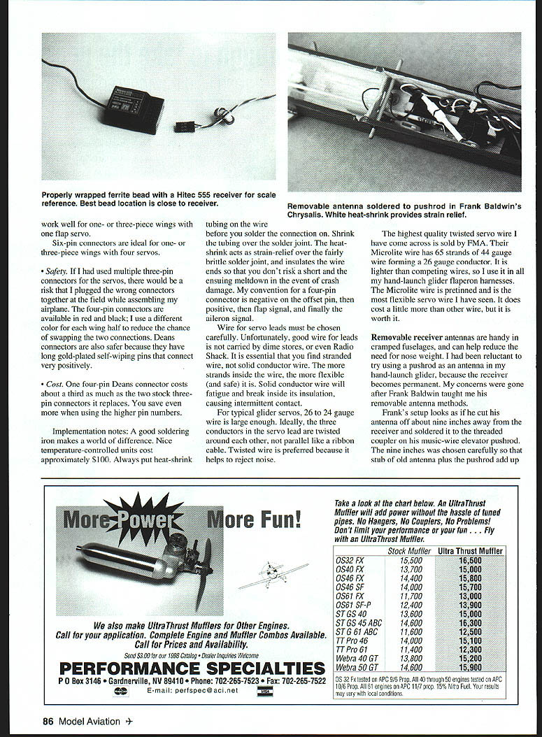
- The best location for the bead is close to the receiver.
- Each bead will act as a filter, reducing the strength of noise in its design frequency range.
Ferrite beads have been proven very effective at eliminating servo jitter. I install them in my large, expensive gliders before testing them because it is cheap insurance.
If servos still twitch
It is also possible to pick up noise in the signal going from the receiver to the servo. If you are using modern servos and your ailerons twitch, this may be the problem. In that case, install a bead near the servo to filter out the noise. Older-style servos often twitch because the potentiometer inside is dirty or needs to be lubricated. The pots in newer servos don't appear to need this treatment as often, if at all.
If cheap methods do not solve the problem, try these options:
- Noise traps (inline filters) from suppliers such as Ace R/C.
- Two or more receivers in the airplane, each with short wires — an expensive solution that works well for large airplanes.
- Special receivers with optically isolated servos — another costly method used by some Europeans.
Connectors: why I use Deans
For the servo lead connections between the wing and the fuselage, I use Deans connectors. There are several good reasons why I choose Deans over the stock Airtronics connectors that plug into my receiver:
- Convenience
- W.S. Deans Company makes connectors with many different pin counts. I can install a four-pin connector at the root of each wing half. The aileron and flap servo for that wing half are joined to a single four-pin connector, sharing the positive and negative pins, so I have just one connector to plug in as I put each wing on the fuselage.
- For a two-piece wing with three servos per side, a five-pin connector is useful. Five-pin connectors also work well for one- or three-piece wings with four servos.
- Safety
- Using multiple three-pin connectors risks plugging the wrong connectors together while assembling the airplane in the field.
- Four-pin connectors are available in red and black; use different color wing halves to reduce the chance of swapping connections.
- Deans connectors have long gold-plated self-wiping pins which connect very positively.
- Cost
- A four-pin Deans connector costs about one-third as much as two stock three-pin connectors it replaces, saving money when you use higher pin numbers.
Soldering and implementation notes
A good soldering iron makes the world of difference. Nice temperature-controlled units cost approximately $100. Always put heat-shrink tubing on the wire before you solder the connection. Shrink the tubing over the solder joint. The heat-shrink acts as strain relief over the fairly brittle solder joint and insulates the wire ends so that you don't risk a short and the ensuing meltdown in the event of crash damage.
My convention for a four-pin connector is: negative on the offset pin, then positive, then flap signal, and finally the aileron signal.
Wire selection and construction
Wire for servo leads must be chosen carefully. It is essential that you find stranded wire, not solid conductor wire. The more strands inside the wire, the more flexible (and safe) it is. Solid conductor wire will fatigue and break inside its insulation, causing intermittent contact.
For typical glider servos, 26 to 24 gauge wire is large enough. Ideally, the three conductors in the servo lead are twisted around each other, not parallel like a ribbon cable. Twisted wire is preferred because it helps to reject noise.
The highest quality twisted servo wire I have come across is sold by FMA. Their Microlite wire has 65 strands of 44-gauge wire forming a 26-gauge conductor. It is lighter than competing wires, so I use it in all my hand-launch glider flaperon harnesses. The Microlite wire is pre-tinned and is the most flexible servo wire I have seen. It does cost a little more than other wire, but it is worth it.
Removable receiver antennas
Removable receiver antennas are handy in cramped fuselages and can help reduce the need for nose weight. I had been reluctant to try using a pushrod as an antenna in my hand-launch glider because the receiver becomes permanent. My concerns were gone after Frank Baldwin taught me his removable antenna methods.
Frank's setup looks as if he cut his antenna off about nine inches away from the receiver and soldered it to the threaded coupler on his music-wire elevator pushrod. The nine inches was chosen carefully so that the stub of old antenna plus the pushrod add up to approximately one-quarter wavelength. White heat-shrink provides strain relief where you solder the connection on. Shrink the tubing over the solder joint. Carefully adjust the length so that the total length from the receiver to the end of the pushrod equals the original antenna length. Count only the part of the pushrod from the solder joint and back — not the one inch or so going from the solder joint to the servo. It is important to give the joint enough space for full servo travel, but still minimize the unsupported length of the pushrod.
What makes Frank's receiver non-permanent is the two-pin Deans connector in-line in the nine-inch antenna stub, about six inches from the receiver. He solders the antenna to both pins of the Deans connector for additional safety.
Non-metal pushrod option
Another option for gliders that do not have metal pushrods is to make the removable antenna from very light wire. I use "magnet wire," which is 30 gauge or smaller enamelled wire. It is solid (single-strand), so you have to mount it in place where it will not get flexed. Usually I mount it permanently in the airframe with a little bit of flexible wire in series at the front end of the airplane.
One nose-weight-saving tip is to mount the antenna in the lighter of your two wings. The flexible part of the wire is soldered to the two-pin Deans connector.
If convenience, not weight, drives your need for a removable antenna, just use the wire from your existing antenna with the Deans connector inserted in it. This wire is most likely multi-strand and thus can be safely flexed. FMA Microlite wire would also be ideal for this use. Remember that the total length, with connector, must remain the same.
Standardization is important if you have many airplanes. Frank always makes the lead from his receiver to his Deans connector exactly six inches so that he can swap receivers among all of his models.
Acknowledgments
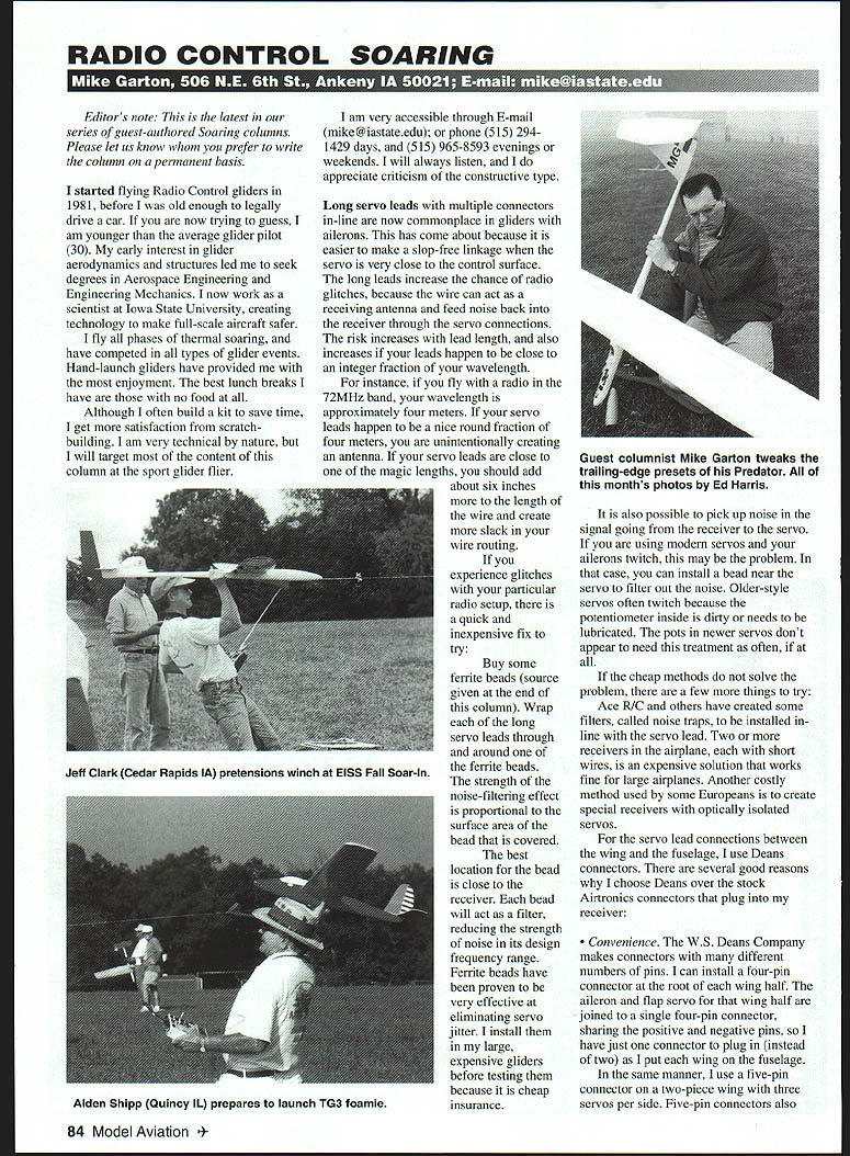
Thanks to Ed Harris, Ankeny, Iowa, for providing this month's photographs.
Sources
- Ferrite beads: Voltz dealers; for instance, Hobby Club, 931 Calle Negocio—Ste "F", San Clemente CA 92673; Tel.: (949) 498-5377; Web site: hobbyclub.com.
- Noise traps: Ace R/C dealers; for instance, Sky Hobby, 1810 Main St., Higginsville MO 64037; Tel.: (800) 241-7556; Web site: skyhobby.com.
- Deans connectors: Local hobby retailers or W.S. Deans Co., 7628 Jackson St., Paramount CA 90723; Tel.: (562) 634-9401; Web site: wsdeans.com.
- Microlite wire: FMA Direct, 9607 Dr. Perry Rd. #109, Jarrettsville MD 21754; Tel.: (800) 343-2934; Web site: fmadirect.com.
- Magnet wire: Try your local electronic store — for instance, Radio Shack; Tel.: (800) 843-7422; Web site: radioshack.com.
Transcribed from original scans by AI. Minor OCR errors may remain.

