
RADIO CONTROL SOARING
Mike Garton 506 NE 6th St., Ankeny IA 50021 E-mail: mike@iastate.edu
Editor's note
We are pleased to welcome Mike Garton aboard as the full-time "RC Soaring" columnist. Mike's initial column generated quite a bit of favorable response from readers.
Mike will cover slope and thermal soaring in a combined format rather than the separate columns run in the past. Please give him plenty of support as he reports on the full spectrum of RC soaring.
Column introduction
Thanks for choosing me as the new Soaring columnist. I will do my best to publish a variety of thermal and slope soaring topics. Please send interesting soaring pictures with caption information. If you scratch-build, send photos and explain what makes your airplane unique.
Focus — Hand-Launch Glider
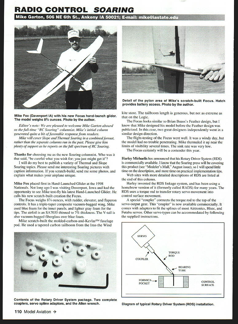
Mike Fox placed first in Hand-Launch Glider at the 1998 Nationals. While visiting Davenport, Iowa, I saw Mike test-fly his latest hand-launch glider, which he calls Focus.
- Weight: 8-3/4 ounces
- Controls: rudder, elevator, flaperons
- Wing: triple-taper composite vacuum-bagged; inner panels of blue foam, lighter gray foam tips
- Airfoil: SA7035 thinned to 7% thickness
- Tail: vacuum-bagged fiberglass V-tail over blue foam
- Fuselage: scratch-built molded carbon-and-Kevlar™ pod
- Tailboom: tapered carbon tailboom (Into the Wind kite store); length generous but not as extreme as the Logic
The Focus looks similar to Brian Buas's Feather design, but Mike designed his model before the Feather design was publicized — two designers independently went in a similar direction.
Flight-testing went well. It was a windy day, but the model penetrated without trouble. Mike thermaled it up near visibility limits several times; sink rate was very low. Focus should be a contender this year.
Rotary Driver System (RDS)
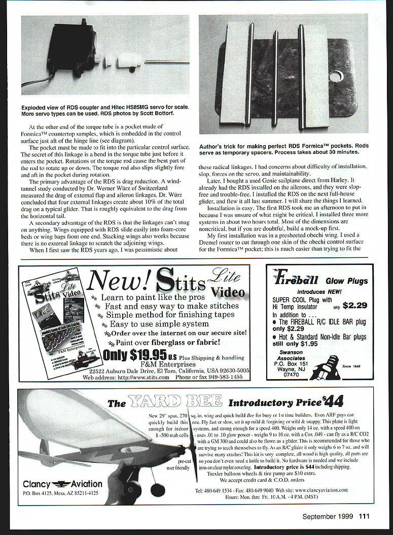
Harley Michaelis has announced that his Rotary Driver System (RDS) is commercially available. The RDS linkage system (formerly called RADS) uses a torque rod to transfer rotary servo movement into control-surface movement.
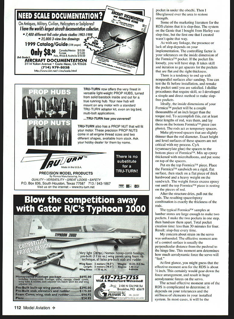
- A special coupler connects the torque rod to the top of the servo output gear. The commercial coupler comes with adapters for splines of most Airtronics, Hitec, and Futaba servos; other servo types can be accommodated per the supplied instructions.
- The other end of the torque rod uses a bearing tube and a Formica™ pocket embedded in the control surface just aft of the hinge line. The pocket must be fitted to the particular control surface.
- The secret of the linkage is a bend in the torque rod just before it enters the pocket. Rotations of the torque rod cause the bent part to rotate up and down; the torque rod also slips slightly fore and aft in the pocket during rotation.
Advantages of RDS
- Primary: drag reduction. A wind-tunnel study by Dr. Werner Wurz (Switzerland) measured drag from external flap/aileron linkages and concluded that four external linkages can create about 10% of the total drag of a typical glider — roughly equivalent to the drag of the horizontal tail.
- Secondary: no snagging. Wings with RDS slide easily into foam-core saddle wing bags, and end-stacking wings is safer because there are no external linkages to scratch adjoining wings.
RDS installation and notes
I was initially pessimistic about RDS — concerned about difficulty of installation, slop, servo forces, and maintainability. After seeing a Genie sailplane with RDS and installing RDS on my next full-house glider, I learned the system is practical and reliable when done correctly.
- Installation is straightforward. My first install took an afternoon; subsequent three systems took about two hours total.
- Most dimensions are noncritical; you probably won't need a mock-up unless you prefer one.
- If your wing is presheeted with obechi, it is easier to cut through one skin of the control surface to fit the Formica™ pocket rather than try to fit the pocket between skins. After embedding the pocket, restore strength by fiberglassing the area.
Slop and tolerances
- Whether an RDS installation has slop depends on your tolerances for the inside dimension of the Formica™ pocket.
- A loose pocket yields slop. It takes iteration to get spacers flat and the correct thickness; there is a tendency to end up with nonparallel surfaces after sanding.
- I developed a simple method to make slop-free pockets (see next section).
Making slop-free Formica™ pockets
Aim for inside pocket dimensions a couple thousandths of an inch larger than the torque rod. My method:
- Cut at least three lengths of torque rod, wax them, and lay them on the bottom piece of Formica™ to act as temporary spacers.
- Make plywood spacers slightly thinner than the rod diameter (exact height and level surfaces are not critical with this method).
- CyA (cyanoacrylate) glue the plywood spacers to the bottom Formica™ piece.
- Mix epoxy thickened with microballoons and put some on top of the spacers.
- Place the top Formica™ piece on the sandwich. Put the Formica™ sandwich on a rigid, flat surface, stack a pair of pieces of thick hardwood on top, and apply a heavy weight.
- When the epoxy cures, pull out the rods. The spacer/epoxy combination will be exactly the thickness of the rods.
- Typical Formica™ samples at lumber stores are large enough to make two pockets; make two pockets in one step and bandsaw them apart.
- Total pocket-creation time: under 30 minutes for four pockets. Result: slop-free every time.
Servo loads, moment arms, and flutter
My concern about strain on servos proved unfounded. The effective moment arm for control force is usually the perpendicular distance from the pushrod to the hinge line. For RDS, the effective moment arm depends on tolerances and stiffness of the installation; in many Three Meter glider installations it is about 3/4 inch (distance between the free tip of the bent torque rod and the hinge line).
- The aerodynamic force transferred to the servo is similar to a standard external linkage with a 3/4-inch control horn.
- You can scale RDS for larger or smaller airplanes; compare the RDS effective moment arm to a properly sized external control horn.
- Flutter is no more likely than with other linkages when installed correctly.
Maintainability and failure modes
I tested RDS over a year. My installation included flaps capable of 90° down travel. Landings on flaps can overload something:
- Formica™ pockets are strong. If you use plastic-geared servos, expect stripped gears under overload.
- With metal-geared servos, the joint between the torque rod and the servo coupler is the likely point of failure: the coupler setscrew will slip and gouge the torque rod.
- The commercial RDS couplers are designed for easier removal; the setscrew allows quick replacement. If servos are accessible, this maintenance can be done between contest rounds.
Sources
- Tapered carbon tailbooms:
Into the Wind kite store, Boulder CO (800) 204-5483 http://www.intothewind.com
- Logic HLG:
Northeast Sailplane Products 16 Kirby Ln., Williston VT 05495 (802) 658-9482 http://www.nesail.com
- Feather HLG:
Raptor Aerosports 9710 Zelzah Ave. #108, Northridge CA 91325 (818) 993-0570 http://www.raptorrc.com
- RDS:
Distributed through Great Planes and Horizon to most hobby stores. Ask about them at your local hobby store.
- Detailed RDS information:
http://www.hollyday.com/rads/rads.htm http://bmi.net/prop/rds
- Drag of external linkages study:
http://bcedel.c.eas.dlr.de/Airfoils/linkage.htm
Transcribed from original scans by AI. Minor OCR errors may remain.

