
Radio Control: Soaring
Dan Pruss
Keeping up with technology — Soar Tech
Through the combined efforts of Jim Gray (RC Soaring editor, Model Airplane News) and Herk Stokely (member, Tidewater Model Soaring Society; editor/contributor to that club's newsletter), a brand-new publication called Soar Tech is available. The first edition is a compilation of contributions from many modelers and includes:
- A procedure for running a sailplane performance program using the TI-59 pocket computer.
- Excerpts from Dieter Althaus's recent book on model-aircraft airfoil sections.
- A contribution by Ken Bates on experimental development of flying-wing designs.
- A study by Al Scidmore on batteries for cold-weather flying.
- Other technical articles and papers.
This first issue is a fine effort. Order from Herk Stokely, 1504 Horseshoe Circle, Virginia Beach, VA 23451. (Price listed in early pressings was $10.)
News from Switzerland — International RC Soaring Flight Forum (ISF)
The photos this month were taken while attending the International RC Soaring Flight Forum (ISF) in Switzerland. These forums have been held since 1978 and were originally instituted by Austria's Fridolin Fritz Dassel and by Hansruedi Schläpfer and Helmut Wehren of Switzerland — all of whom were driving forces behind the Spartakus design and construction techniques.
Over the years the ISF has become a focal point for showing new designs, new building materials, and new building techniques. New airfoil studies have made their debuts there, and guest speakers have included Dr. Eppler himself. The forum is a full two-day session, supplemented by a set of papers similar in format to Soar Tech's. This year over 150 modelers attended.
Airfoil turbulation and the blasturbulator
It's long been known that certain airfoils, when turbulated near the leading edge, will produce more lift at lower speeds than the same wing in a clean configuration. Dieter Althaus's figures show, for example, that a turbulated Eppler 193 has a slight edge over the clean version at slower speeds, but that turbulation is detrimental in higher-speed tasks such as F3B Speed and Distance. In Althaus's tests the turbulator was only a strip of 1/16-inch Mylar tape.
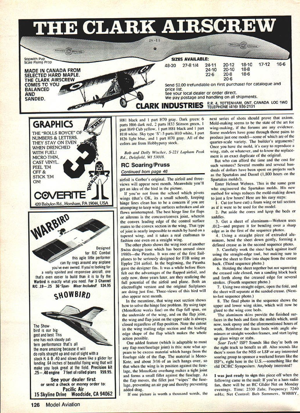
Rolf Girsberger and Hans Senn developed an active system — loosely called a blasturbulator — that uses ram air to create turbulation on demand. The system works like this:
- A hole in the nose of the fuselage scoops ram air.
- The air is routed through internal plumbing and into full-span tubes in the wings.
- A valve in the fuselage controls airflow into the wing tubes.
- Small holes are drilled from the wing surface into the tubing; when the valve opens, air escapes through those pinholes and acts as a turbulator.
The system is effective at low speeds, but it has drawbacks: at slow flight speeds not enough air can be scooped through the nose, and much of the air is bled off before reaching the outer wing sections. Adding a small air pump and an accumulator was discussed as a possible improvement.
Sharing ideas
These forums are for the exchange of ideas. If any secrets are kept, they are well hidden — but the biggest names in Swiss modeling gathered to offer their latest work. For example, Peter Gerber showed his newest design, the Gamma, two of which placed on the 1983 Swiss F3B team. The Gamma is a clean, beautifully finished design featuring a pivoting wing: rather than using ailerons or flaperons, each wing panel is driven by a servo and pivots about the main spar. The airfoil is Gerber's original; airfoil data and three-views will appear next month.
Wing hinge lines and flap/fuselage joins
If you favor a continuous, unbroken wing surface, keeping hinge lines clean is essential. The best hinge for flaps or ailerons is the concave/convex joint, wherein the convex leading edge of the control surface mates to the concave section in the wing. That type of joint is difficult to match by hand on a tapered wing and takes a real craftsman even on a straight wing.
One Swiss design — the Piranha, in production since 1980 — was among the first sailplanes seriously designed for F3B using an Eppler 214 airfoil. Initially the Piranha gave its designer fits; it took a while for fliers to exploit the advantages of the flapped airfoil. Three years on, both the original sailplane and an electrolight version are doing well. Three-views of the Piranha will appear next month.
A practical hinge/wing-root solution used on the Piranha demonstrates how to keep the upper-surface joint closed regardless of flap position:
- Use tape (Monokote works fine) full-span on the underside of the wing and on the flap joint.
- Cut a trailing-edge recess in the wing and shape the flap's leading edge so the upper-surface joint stays closed in all flap positions.
- Allow about 3/16-inch of Monokote to overhang from the fuselage side of the flap so that when the wing is installed the overhang forms a tight fillet against the fuselage. As the flap moves the fillet wipes the fuselage, preventing an air gap and reducing drag.
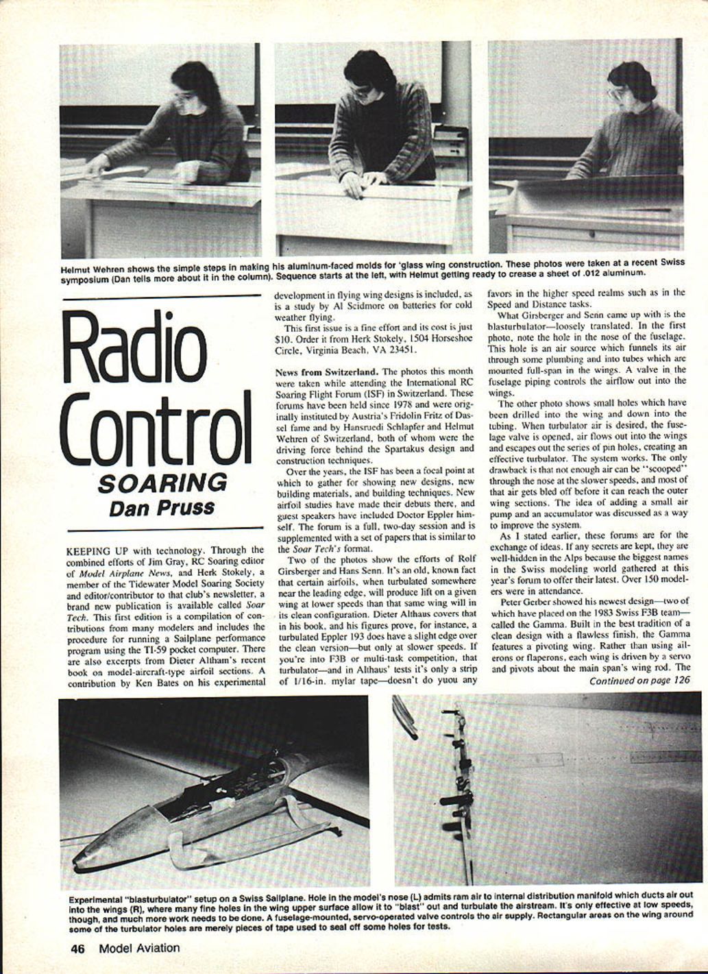
Mold-making — Helmut Wehren's rapid method
Mold-making has been a state-of-the-art method for reproducing wings and other parts, but traditional molds can take months and cost hundreds or thousands of dollars to produce. Helmut Wehren — the same engineer behind the Spartakus molds — demonstrated a new method that reduces wing-mold making to just a few hours. His simplified process:
- Cut (or have cut) a foam wing or tail section as if it were to be used for the model.
- Put aside the cores and keep the beds or saddles.
- Get a sheet of aluminum (Wehren uses .012") and prepare it for bending over a sharp edge.
- Using a straight piece of extruded aluminum, bend the sheet down gently to form a defined crease.
- Carefully work the sheet back against itself using the straight-edge tool, allowing the sheet to flow into the wing shape from the crease.
- Holding the sheet together but not squeezing the creased side closed, run a sanding block back and forth along the creased edge for several strokes.
- Using two straight edges, open the fold; the sheet will separate at the sanded crease.
- The resulting upper and lower aluminum skins can now be glued to the wing core beds.
The aluminum skins provide finished surfaces in the beds and form molds that previously required epoxy and many hours of work. Reinforce the foam beds with angle aluminum or straight wooden frames, then lay up glass skins over the molds.
Closing thoughts and contacts
Soar Tech and the ISF are both on the right track to benefit the modeling community. There's room for the NSS, LSF, or any interested group to sponsor a weekend forum like the ISF here in the U.S. — something along the lines of the old DC/RC Symposium. Anybody interested?
If you're a ham radio fan, there is an RC Glider Net on Monday evenings:
- Time: 2330 Zulu
- Frequency: 7240 kHz
- Net Control: Bob Summers, WB8BY
Transcribed from original scans by AI. Minor OCR errors may remain.

