
Radio Control: Soaring
Dan Pruss
Good and Bad
During 1982, the U.S.A./F3B team selection program indicated two possible trends, one positive, one negative. On the positive side, participation was up. As a matter of fact, more fliers qualified for the semifinals in 1982 than entered the quarterfinals in 1980. On the negative side, fewer contests were held in 1982, and only one bid was made to run the Finals.
While individual interest is expected to grow, if soaring were to follow past trends, the club activity in the form of contests should grow also. It hasn't worked that way with F3B.
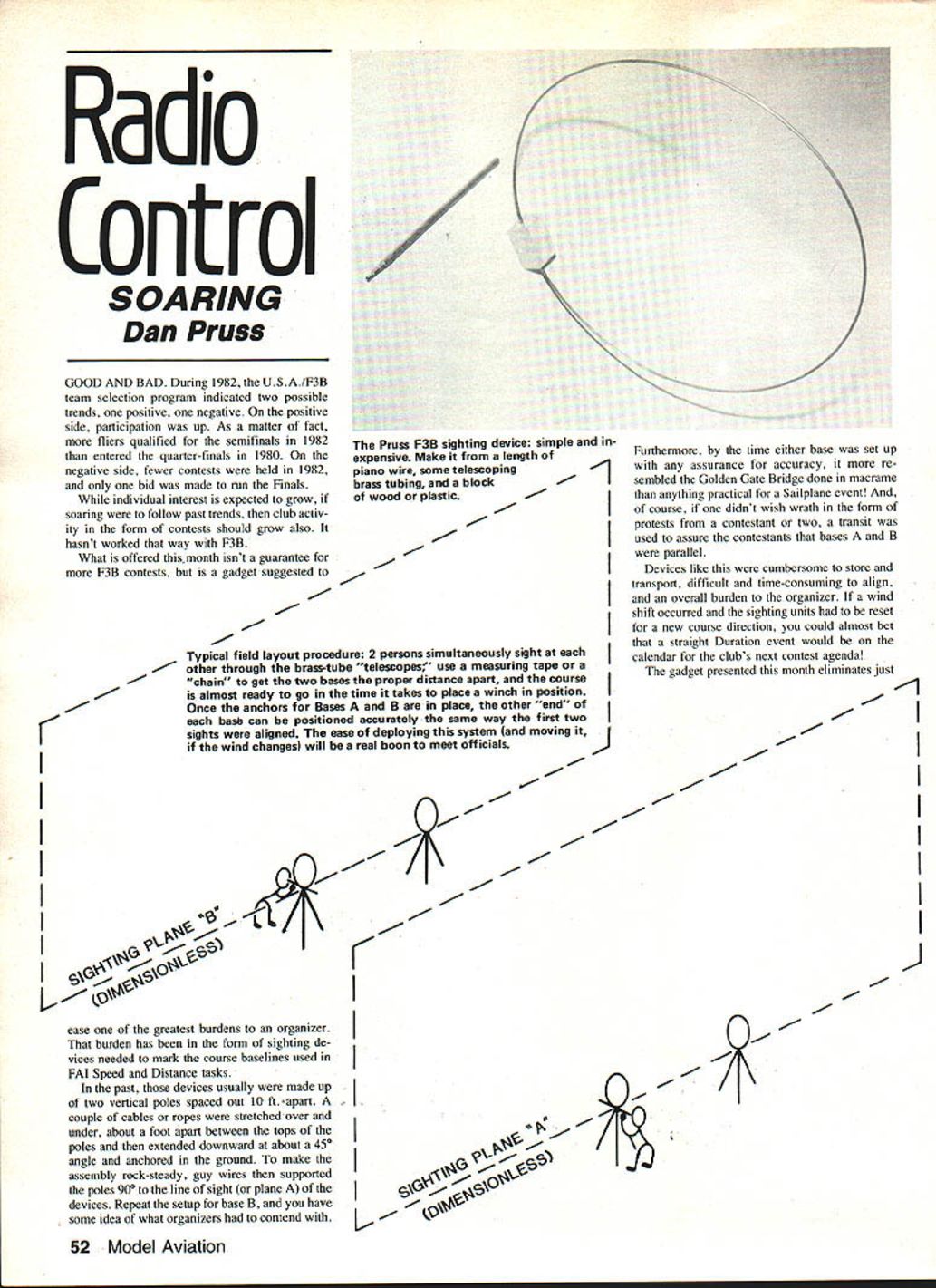
What is offered here isn't a guarantee for more F3B contests, but is a gadget suggested to ease one of the greatest burdens to an organizer.
The Problem with Traditional Sighting Devices
That burden has been in the form of sighting devices needed to mark the course baselines used in FAI Speed and Distance tasks.
In the past, those devices usually were made up of two vertical poles spaced about 10 ft. apart. A couple of cables or ropes were stretched over and under, about a foot apart, between the tops of the poles and then extended downward at about a 45° angle and anchored in the ground. To make the assembly rock-steady, guy wires then supported the poles 90° to the line of sight (or plane A) of the devices. Repeat the setup for base B, and you have some idea of what organizers had to contend with.
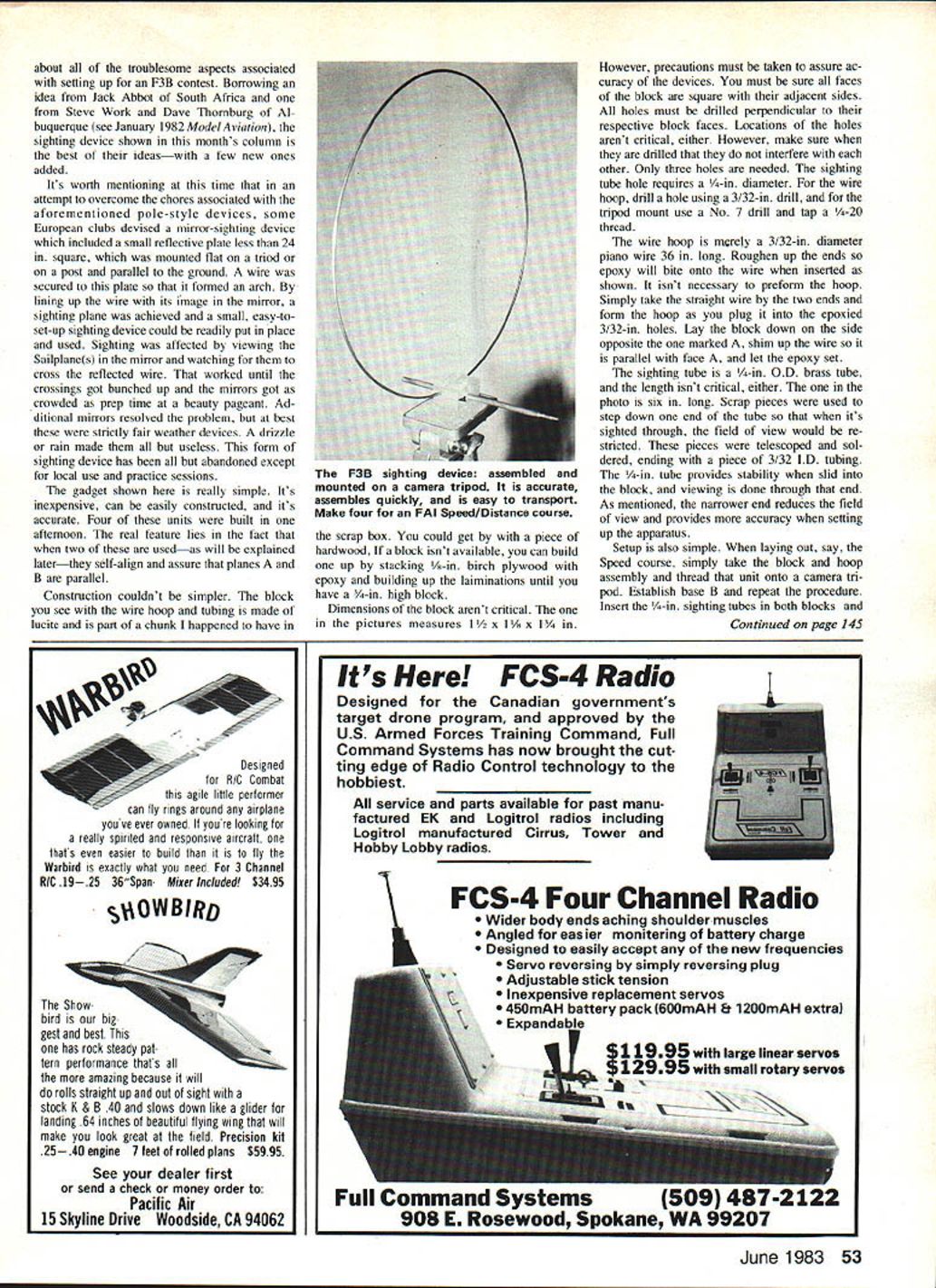
Typical field layout procedure: two persons simultaneously sight at each other through the brass-tube "telescopes"; use a measuring tape or a "chain" to get the two bases the proper distance apart, and the course is almost ready to go in the time it takes to place a winch in position. Once the anchors for Bases A and B are in place, the other "end" of each base can be positioned accurately the same way the first two sights were aligned. The ease of deploying this system (and moving it, if the wind changes) would be a real boon to meet officials.
By the time either base was set up with any assurance for accuracy, it more resembled the Golden Gate Bridge done in macramé than anything practical for a sailplane event! And, of course, if one didn't wish wrath in the form of protests from a contestant or two, a transit was used to assure the contestants that bases A and B were parallel.
Devices like this were cumbersome to store and transport, difficult and time-consuming to align, and an overall burden to the organizer. If a wind shift occurred and the sighting units had to be reset for a new course direction, you could almost bet that a straight Duration event would be on the calendar for the club's next contest agenda!
Some European clubs tried mirror-sighting devices: a small reflective plate mounted parallel to the ground on a tripod or post, with a wire forming an arch above it. By lining up the wire with its image in the mirror, a sighting plane was achieved and a small, easy-to-set-up device could be used. Sighting was done by viewing the sailplane(s) in the mirror and watching for them to cross the reflected wire. That worked until crossings got bunched up and mirrors became crowded. Additional mirrors helped, but these devices were fair-weather only—drizzle or rain made them all but useless. This form of sighting device has been largely abandoned except for local use and practice sessions.
The New Gadget
The gadget shown here is really simple, inexpensive, easy to construct, and accurate. Four units were built in one afternoon. The real feature is that when two of these are used together they self-align and assure that planes A and B are parallel.
The idea borrows from Jack Abbot of South Africa and Steve Work and Dave Thornburg of Albuquerque (see January 1982 Model Aviation), with a few new additions.
Construction
Materials and general notes:
- Block: lucite or hardwood; alternatively, stack 5/8-in. birch plywood laminated with epoxy to reach about 3/4-in. high.
- Block dimensions are not critical. Example block: 1 1/2 x 1 1/8 x 1 1/4 in.
- Ensure all faces of the block are square and all holes are drilled perpendicular to their respective faces.
- Only three holes are needed.
Holes and fittings:
- Sighting tube hole: 1/4-in. diameter.
- Wire hoop holes: use a 3/32-in. drill.
- Tripod mount: use a No. 7 drill and tap a 1/4-20 thread.
Wire hoop:
- Use 3/32-in. diameter piano wire, 36 in. long.
- Roughen the ends so epoxy will bond.
- No need to preform the hoop: insert the straight wire ends into the epoxied holes, then form the hoop in place.
- Lay the block down on the side opposite the one marked A, shim the wire so it is parallel with face A, and let the epoxy set.
Sighting tube:
- Use a 1/4-in. O.D. brass tube; length isn't critical (example: 6 in.).
- To restrict the field of view for increased accuracy, step down one end using telescoped scrap pieces, ending with a piece of 3/32-in. I.D. tubing. Solder these pieces together.
- The 1/4-in. tube gives stability when slid into the block; viewing is done through the larger end and the narrower end reduces the field of view.
Cost: less than $6 per unit. All parts are locally available. Blocks can be cut from scrap and brass for sighting tubes can be scavenged from old camera tripod supports.
Setup and Use
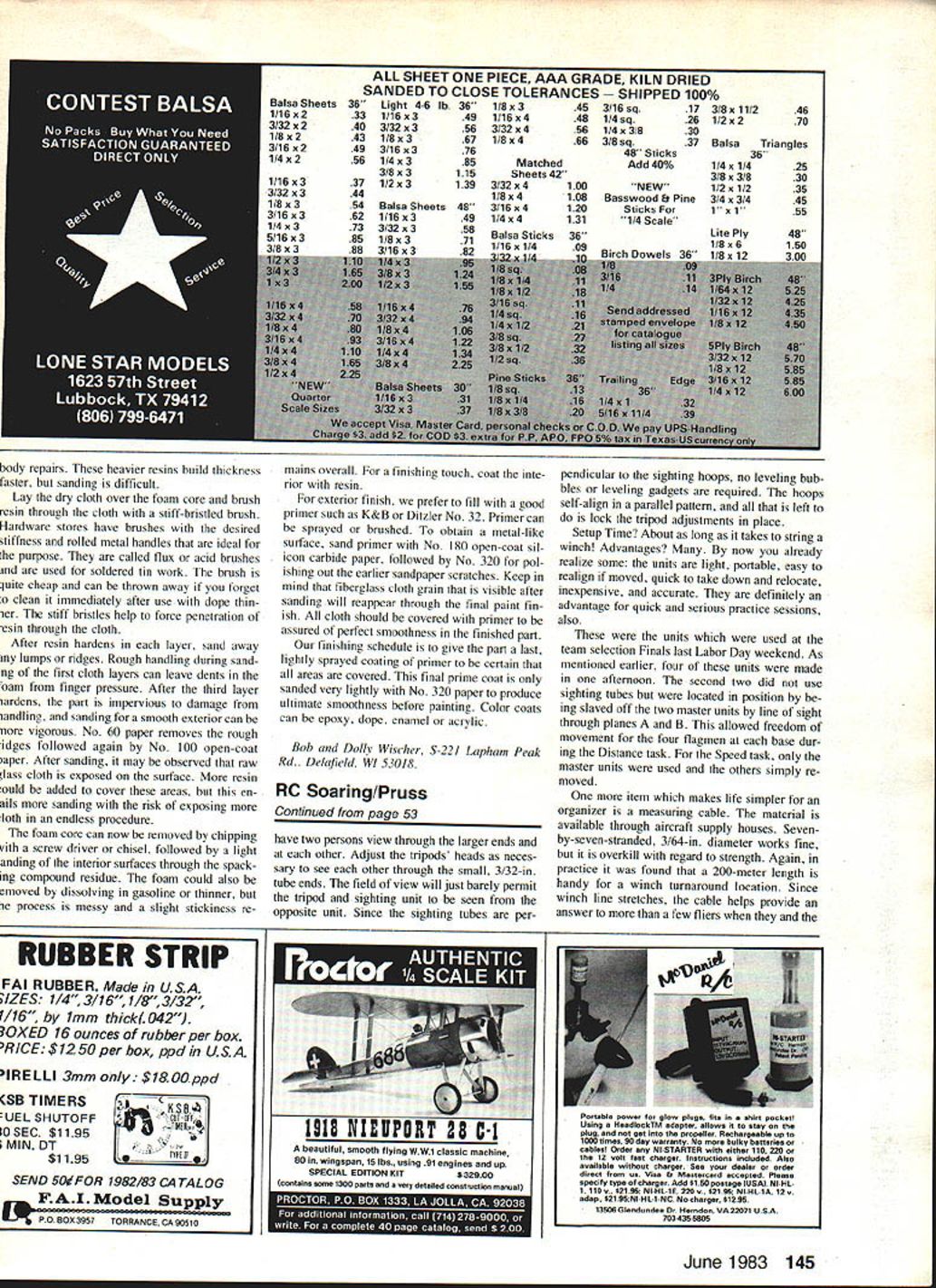
- Mount the block and hoop assembly on a camera tripod.
- Establish base B and repeat the procedure for base A.
- Insert the 1/4-in. sighting tubes in both blocks.
- Have two persons view through the larger ends and sight each other through the smaller 3/32-in. ends.
- Adjust the tripod heads as necessary until each unit can just see the other through the narrow end.
- Because the sighting tubes are perpendicular to the sighting hoops, no leveling bubbles or gadgets are required—the hoops self-align in parallel.
- Lock the tripod adjustments in place.
Setup time: about as long as it takes to string a winch. Advantages include:
- Light and portable
- Easy to realign if moved
- Quick to take down and relocate
- Inexpensive
- Accurate
- Useful for quick and serious practice sessions
At the team selection Finals last Labor Day weekend, four of these units were used. Two units served as masters with sighting tubes; the other two were slaved off the master units by line of sight through planes A and B. This allowed freedom of movement for four flags at each base during the Distance task. For the Speed task, only the master units were used.
Measuring Cable
One more item that simplifies organization is a measuring cable. Material is available through aircraft supply houses. Seven-by-seven stranded, 3/64-in. diameter wire works well (though it is overkill in strength). A 200-meter length is handy for a winch turnaround location. Since winch line stretches, the cable helps settle questions about true takeoff distance and avoids arguments and protests.
Markings on the cable:
- 150-meter mark: a link to indicate the length of the Distance and Speed courses.
- Additional links at quarter-, half-, and three-quarter-lap marks.
Recommendation and Closing
For any serious organizer of an F3B contest—or any serious competitor—the sighting devices and measuring cable are highly recommended. Novices in your club could whip up a set of eight in a couple of hours and help make your next soaring contest go easier.
Support your U.S.A./F3B team. Team Manager Dick Oede announced that patches are available for $6, pins for $5, and decals for $3. Send payments to:
- Dick Oede
- 815 Mellow Lane
- Simi Valley, CA 93065
Good lift.
Dan Pruss 131 E. Pennington Ln. Plainfield, IL 60544
Transcribed from original scans by AI. Minor OCR errors may remain.

